Este PDF no está enlazado desde ningún artículo publicado.
Página 1 — T-REC-T.38-201009-IPDF-E-1

I n t e r n a t i o n a l T e l e c o m m u n i c a t i o n U n i o n
ITU-T
T.38
TELECOMMUNICATION
STANDARDIZATION SECTOR
OF ITU
(09/2010)
SERIES T: TERMINALS FOR TELEMATIC SERVICES
Facsimile – Group 3 protocols Procedures for real-time Group 3 facsimile communication over IP networks Recommendation ITU-T T.38
Página 2 — T-REC-T.38-201009-IPDF-E-1
ITU-T T-SERIES RECOMMENDATIONS
TERMINALS FOR TELEMATIC SERVICES
Facsimile – Framework Still-image compression – Test charts Facsimile – Group 3 protocols Colour representation Character coding Facsimile – Group 4 protocols Telematic services – Framework Still-image compression – JPEG-1, Bi-level and JBIG Telematic services – ISDN Terminals and protocols Videotext – Framework Data protocols for multimedia conferencing Telewriting Multimedia and hypermedia framework Cooperative document handling Telematic services – Interworking Open document architecture Document transfer and manipulation Document application profile Communication application profile Telematic services – Equipment characteristics Still-image compression – JPEG 2000 Still-image compression – JPEG XR Still-image compression – JPEG-1 extensions For further details, please refer to the list of ITU-T Recommendations.
T.0–T.19
T.20–T.29
T.30–T.39
T.40–T.49
T.50–T.59
T.60–T.69
T.70–T.79
T.80–T.89
T.90–T.99
T.100–T.109
T.120–T.149
T.150–T.159
T.170–T.189
T.190–T.199
T.300–T.399
T.400–T.429
T.430–T.449
T.500–T.509
T.510–T.559
T.560–T.649
T.800–T.829
T.830–T.849
T.850–T.899
Página 3 — T-REC-T.38-201009-IPDF-E-1
Recommendation ITU-T T.38 Procedures for real-time Group 3 facsimile communication over IP networks Summary Recommendation ITU-T T.38 defines the procedures to be applied to allow Group 3 facsimile transmission between terminals where, in addition to the public switched telephone network (PSTN) or integrated services digital network (ISDN), a portion of the transmission path used between terminals includes an IP network, e.g., the Internet.
This revision of this Recommendation clarifies Recommendation ITU-T H.323, Recommendation ITU-T H.248.1, session initiation protocol (SIP) and session description protocol (SDP) call establishment and improves the compatibility between ITU-T T.38 gateways and Group 3 facsimile.
History Edition Recommendation Approval Study Group 1998-06-18 8 1.1 ITU-T T.38 (1998) Amd. 1 1999-04-01 8 1.2 ITU-T T.38 (1998) Amd. 2 2000-02-10 8 1.3 ITU-T T.38 (1998) Cor. 1 2000-03-30 8 1.4 ITU-T T.38 (1998) Amd. 3 2000-11-17 16 1.5 ITU-T T.38 (1998) Amd. 4 2001-07-29 16 1.0 2.0
ITU-T T.38
ITU-T T.38
2002-03-29 16 2.1 ITU-T T.38 (2002) Cor. 1 2003-07-14 16 2.2 ITU-T T.38 (2002) Amd. 1 2003-07-29 16 2.3 ITU-T T.38 (2002) Amd. 3 2004-01-30 16 2.4 ITU-T T.38 (2002) Amd. 2 2004-04-22 16 3.0 3.1
ITU-T T.38
2004-04-22 16 ITU-T T.38 (2004) Amd. 1 2005-01-08 16 4.0
ITU-T T.38
2005-09-13 16 5.0
ITU-T T.38
2007-04-06 16 6.0
ITU-T T.38
2010-09-13 16 Rec. ITU-T T.38 (09/2010) i
Página 4 — T-REC-T.38-201009-IPDF-E-1
FOREWORD
The International Telecommunication Union (ITU) is the United Nations specialized agency in the field of telecommunications, information and communication technologies (ICTs). The ITU Telecommunication Standardization Sector (ITU-T) is a permanent organ of ITU. ITU-T is responsible for studying technical, operating and tariff questions and issuing Recommendations on them with a view to standardizing telecommunications on a worldwide basis.
The World Telecommunication Standardization Assembly (WTSA), which meets every four years, establishes the topics for study by the ITU-T study groups which, in turn, produce Recommendations on these topics.
The approval of ITU-T Recommendations is covered by the procedure laid down in WTSA Resolution 1.
In some areas of information technology which fall within ITU-T's purview, the necessary standards are prepared on a collaborative basis with ISO and IEC.
NOTE
In this Recommendation, the expression "Administration" is used for conciseness to indicate both a telecommunication administration and a recognized operating agency.
Compliance with this Recommendation is voluntary. However, the Recommendation may contain certain mandatory provisions (to ensure, e.g., interoperability or applicability) and compliance with the Recommendation is achieved when all of these mandatory provisions are met. The words "shall" or some other obligatory language such as "must" and the negative equivalents are used to express requirements. The use of such words does not suggest that compliance with the Recommendation is required of any party.
INTELLECTUAL PROPERTY RIGHTS
ITU draws attention to the possibility that the practice or implementation of this Recommendation may involve the use of a claimed Intellectual Property Right. ITU takes no position concerning the evidence, validity or applicability of claimed Intellectual Property Rights, whether asserted by ITU members or others outside of the Recommendation development process.
As of the date of approval of this Recommendation, ITU had not received notice of intellectual property, protected by patents, which may be required to implement this Recommendation. However, implementers are cautioned that this may not represent the latest information and are therefore strongly urged to consult the TSB patent database at http://www.itu.int/ITU-T/ipr/.
ITU 2012
All rights reserved. No part of this publication may be reproduced, by any means whatsoever, without the prior written permission of ITU.
ii Rec. ITU-T T.38 (09/2010)
Página 5 — T-REC-T.38-201009-IPDF-E-1
Table of Contents Page 1 Scope ............................................................................................................................
1 2 Normative references ....................................................................................................
1 3 Definitions ....................................................................................................................
3 4 Abbreviations and acronyms ........................................................................................
3 5 Introduction ..................................................................................................................
5.1 Conventions ....................................................................................................
4 7 6 Communication between gateways ..............................................................................
6.1 Internet protocol – TCP or UDP .....................................................................
6.2 Gateway facsimile data transfer functions .....................................................
7 7 7 7 IFT protocol definition and procedures ........................................................................
7.1 General ...........................................................................................................
7.2 IFP packet format ...........................................................................................
7.3 TYPE definitions ............................................................................................
7.4 The IFP DATA element .................................................................................
7.5 Limitation of ITU-T V.21 frame packet size..................................................
8 8 10 11 13 15 8 IFP message flow for facsimile modulations up to ITU-T V.17 ..................................
8.1 Data rate management method 1 ....................................................................
8.2 Data rate management method 2 ....................................................................
15 15 16 9 IFT over UDP transport ................................................................................................
9.1 IFT over UDP transport using UDPTL protocol: IFT/UDPTL/UDP .............
9.2 IFT over UDP transport using RTP protocol: IFT/RTP/UDP ........................
16 16 18 10 Message flow for ITU-T V.8 signals and Annex F of ITU-T V.34 facsimile ..............
10.1 ITU-T V.8 negotiation ....................................................................................
10.2 ITU-T V.34 data rate management .................................................................
10.3 Facsimile mode ...............................................................................................
10.4 Compatibility with equipment conforming to prior versions of this Recommendation ............................................................................................
19 19 21 22 Annex A – ASN.1 notation ......................................................................................................
A.1 ITU-T T.38 (2002) ASN.1 notation ...............................................................
A.2 ITU-T T.38 (1998) ASN.1 notation ...............................................................
25 25 26 Annex B – ITU-T H.323 call establishment procedures ..........................................................
B.1 Introduction ....................................................................................................
B.2 Communication between facsimile terminal and gateway .............................
B.3 Communication between gateways ................................................................
29 29 29 29 Annex C – The optional forward error correction scheme for UDPTL ...................................
C.1 Overview of the optional forward error correction mechanism .....................
C.2 Parity encode/decode scheme operation and characteristics ..........................
36 36 36 Rec. ITU-T T.38 (09/2010) iii 24
Página 6 — T-REC-T.38-201009-IPDF-E-1
Page Annex D – SIP/SDP call establishment procedures ................................................................
D.1 Introduction ....................................................................................................
D.2 Communication between gateways ................................................................
41 41 41 Annex E – ITU-T H.248.1 call establishment procedures .......................................................
E.1 Introduction ....................................................................................................
E.2 Communication between gateways ................................................................
65 65 65 Annex F – Interworking procedures: ITU-T T.38 and ITU-T V.150.1 in the same gateway ..
F.1 Introduction ....................................................................................................
F.2 SSE reason identifier codes for ITU-T T.38 transition ..................................
F.3 Mode override from ITU-T V.34 Group 3 facsimile to standard Group 3 facsimile .........................................................................................................
F.4 External signalling ..........................................................................................
75 75 76 Annex G – ITU-T H.245 capability definition for ITU-T T.38 over RTP ..............................
79 Annex H – Signalled and provisioned ITU-T T.38 protocol parameters.................................
H.1 Introduction ....................................................................................................
H.2 Transport conditional ITU-T T.38 parameters ...............................................
H.3 Guidelines for signalling ITU-T T.38 protocol parameters............................
H.4 Legacy Interpretation of SDP Parameters ......................................................
81 81 81 87 87 Appendix I – Session examples ...............................................................................................
I.1 Session examples ............................................................................................
I.2 IAF device ......................................................................................................
88 88 92 Appendix II – Examples of call establishment procedures described in Annex B of ITU-T T.38 ...............................................................................................................................
II.1
Sequence examples of call establishment procedures ....................................
II.2
Protocol data used in call establishment procedures ......................................
95 95 99 Appendix III – ITU-T H.248 call establishment procedure examples for facsimile-capable media gateways.............................................................................................................
III.1
Introduction ....................................................................................................
III.2
Examples of call setup ....................................................................................
105 105 105 Appendix IV – ITU-T V.34 session examples .........................................................................
IV.1
ITU-T V.34 session examples ........................................................................
135 135 Appendix V – ITU-T T.38 implementation guidelines............................................................
V.1 General issue ..................................................................................................
V.2 IAF issues .......................................................................................................
V.3 Call-setup issues .............................................................................................
V.4 Others .............................................................................................................
146 146 147 147 148 Bibliography.............................................................................................................................
149 iv Rec. ITU-T T.38 (09/2010) 76 78
Página 7 — T-REC-T.38-201009-IPDF-E-1
Recommendation ITU-T T.38 Procedures for real-time Group 3 facsimile communication over IP networks 1 Scope This Recommendation defines the procedures to be applied to allow Group 3 facsimile transmission between terminals where, in addition to the PSTN or ISDN, a portion of the transmission path used between terminals includes an IP network, e.g., the Internet.
2 Normative references The following ITU-T Recommendations and other references contain provisions which, through reference in this text, constitute provisions of this Recommendation. At the time of publication, the editions indicated were valid. All Recommendations and other references are subject to revision; users of this Recommendation are therefore encouraged to investigate the possibility of applying the most recent edition of the Recommendations and other references listed below. A list of the currently valid ITU-T Recommendations is regularly published. The reference to a document within this Recommendation does not give it, as a stand-alone document, the status of a Recommendation.
[ITU-T E.180]
Recommendation ITU-T E.180/Q.35 (1998), Technical characteristics of tones for the telephone service.
[ITU-T F.185]
Recommendation ITU-T F.185 (1998), Internet facsimile: Guidelines for the support of the communication of facsimile documents.
[ITU-T G.711]
Recommendation ITU-T G.711 (1988), Pulse code modulation (PCM) of voice frequencies.
[ITU-T G.729]
Recommendation ITU-T G.729 (2007), Coding of speech at 8 kbit/s using conjugate-structure algebraic-code-excited linear prediction (CS-ACELP).
[ITU-T H.225.0]
Recommendation ITU-T H.225.0 (2003), Call signalling protocols and media stream packetization for packet-based multimedia communication systems.
[ITU-T H.245]
Recommendation ITU-T H.245 (2009), Control protocol for multimedia communication.
[ITU-T H.248.1]
Recommendation ITU-T H.248.1 (2005), Gateway control protocol, Version 3.
[ΙΤU-Τ H.248.2]
Recommendation ITU-T H.248.2 (2005), Gateway control protocol:
Facsimile, text conversation and call discrimination packages.
[ITU-T H.323]
Recommendation ITU-T H.323 (2003), Packet-based multimedia communications systems.
[ITU-T Q.850]
Recommendation ITU-T Q.850 (1998), Usage of cause and location in the Digital Subscriber Signalling System No. 1 and the Signalling System No. 7 ISDN user part.
[ITU-T Q.931]
Recommendation ITU-T Q.931 (1998), ISDN user-network interface layer 3 specification for basic call control.
[ITU-T T.4]
Recommendation ITU-T T.4 (2003), Standardization of Group 3 facsimile terminals for document transmission.
[ITU-T T.6]
Recommendation ITU-T T.6 (1988), Facsimile coding schemes and coding control functions for Group 4 facsimile apparatus.
Rec. ITU-T T.38 (09/2010) 1
Página 8 — T-REC-T.38-201009-IPDF-E-1
[ITU-T T.30]
Recommendation ITU-T T.30 (2005), Procedures for document facsimile transmission in the general switched telephone network.
[ITU-T T.37]
Recommendation ITU-T T.37 (1998), Procedures for the transfer of facsimile data via store-and-forward on the Internet.
[ITU-T T.66]
Recommendation ITU-T T.66 (2002), Facsimile code points for use with Recommendations V.8 and V.8 bis.
[ITU-T V.8]
Recommendation ITU-T V.8 (2000), Procedures for starting sessions of data transmission over the public switched telephone network.
[ITU-T V.21]
Recommendation ITU-T V.21 (1988), 300 bits per second duplex modem standardized for use in the general switched telephone network.
[ITU-T V.33]
Recommendation ITU-T V.33 (1988), 14 400 bits per second modem standardized for use on point-to-point 4-wire leased telephone-type circuits.
[ITU-T V.34]
Recommendation ITU-T V.34 (1998), A modem operating at data signalling rates of up to 33 600 bit/s for use on the general switched telephone network and on leased point-to-point 2-wire telephone-type circuits.
[ITU-T V.150.1]
Recommendation ITU-T V.150.1 (2003), Modem-over-IP networks:
Procedures for the end-to-end connection of V-series DCEs.
[ITU-T V.152]
Recommendation ITU-T V.152 (2010), Procedures for supporting voice-band data over IP networks.
[ITU-T X.420]
Recommendation ITU-T X.420 (1999) | ISO/IEC 10021-7:2003, Information technology – Message Handling Systems (MHS): Interpersonal Messaging System.
[ITU-T X.680]
Recommendation ITU-T X.680 (2002) | ISO/IEC 8824-1:2002, Information technology – Abstract Syntax Notation One (ASN.1): Specification of basic notation.
[ITU-T X.691]
Recommendation ITU-T X.691 (2002) | ISO/IEC 8825-2:2002, Information technology – ASN.1 encoding rules: Specification of Packed Encoding Rules
(PER).
[IETF RFC 768]
IETF RFC 768 (1980), User Datagram Protocol.
[IETF RFC 791]
IETF RFC 791 (1981), Internet Protocol – DARPA Internet Program – Protocol Specification.
[IETF RFC 793]
IETF RFC 793 (1981), Transmission Control Protocol – DARPA Internet Program – Protocol Specification.
[IETF RFC 1006]
IETF RFC 1006 (1987), ISO transport services on top of the TCP: Version 3.
[IETF RFC 2198]
IEFT RFC 2198 (1997), RTP Payload for Redundant Audio Data.
[IETF RFC 2327]
IETF RFC 2327 (1998), SDP: Session Description Protocol.
[IETF RFC 3261]
IETF RFC 3261 (2002), SIP: Session Initiation Protocol.
[IETF RFC 3264]
IETF RFC 3264 (2002), An Offer/Answer Model with Session Description Protocol (SDP).
[IETF RFC 3550]
IETF RFC 3550 (2003), RTP: A Transport Protocol for Real-Time Applications.
[IETF RFC 4733]
IETF RFC 4733 (2006), RTP Payload for DTMF Digits, Telephony Tones and Telephony Signals.
2 Rec. ITU-T T.38 (09/2010)
Página 9 — T-REC-T.38-201009-IPDF-E-1
[IETF RFC 5109]
IETF RFC 5109 (2007), RTP Payload Format for Generic Forward Error Correction.
[IETF RFC 5939]
IETF RFC 5939 (2010), Session Description Protocol (SDP) Capability Negotiation.
[ISO/IEC 8825-2]
ISO/IEC 8825-2:2008, Information technology – ASN.1 encoding rules:
Specification of Packed Encoding Rules (PER).
3 Definitions Unless otherwise noted, the definitions in [ITU-T F.185] shall apply. This Recommendation defines the following terms:
3.1 emitting gateway: The IFP peer which initiates IFT service for a calling G3FE. It initiates a TCP or UDP connection to a receiving gateway to begin an IFT session.
3.2 G3 facsimile equipment (G3FE): In this Recommendation, G3FE refers to any entity which presents a communications interface conforming to [ITU-T T.30], [ITU-T T.4], and, optionally, [ITU-T T.6]. A G3FE may be a traditional G3 facsimile machine, an application with an ITU-T T.30 protocol engine, or any of the other possibilities mentioned in the network model for IP facsimile.
3.3 receiving gateway: The IFP peer which accepts a TCP or UDP connection from an emitting gateway, providing IFT service to a called G3FE.
3.4 ITU-T T.38/G3: In this Recommendation, ITU-T T.38/G3 refers to an ITU-T T.38 endpoint that supports G3FE, but excludes the ITU-T T.30/V.34 procedures.
3.5 ITU-T T.38/ITU-T V.34G3: In this Recommendation, ITU-T T.38/ITU-T V.34G3 refers to an ITU-T T.38 endpoint that supports G3FE and includes the ITU-T T.30/V.34 half-duplex procedures.
4 Abbreviations and acronyms This Recommendation uses the following abbreviations:
ANSam amplitude-modulated ANSwer tone CI Call Indicator (signal) CM Call Menu (signal) CJ Call Menu terminator (signal) ECM Error Correction Mode FD Facsimile Device FEC Forward Error Correction FoIP Facsimile over IP ([ITU-T T.38])
G3FE
Group 3 Facsimile Equipment GW Gateway IAF Internet-Aware Fax device IFP Internet Facsimile Protocol IFT Internet Facsimile Transfer INFOh Half duplex INFO sequence Rec. ITU-T T.38 (09/2010) 3
Página 10 — T-REC-T.38-201009-IPDF-E-1
IP Internet Protocol FoIP Facsimile over IP ([ITU-T T.38])
G3FE
Group 3 Facsimile Equipment GW Gateway
JBIG
Joint Bi-level Image experts Group (ITU-T T.38 coding scheme) JM Joint Menu (signal) LSB Least Significant Bit MG Media Gateway ([ITU-T H.248]) MGC Media Gateway Controller ([ITU-T H.248]) MoIP (Data) Modem over IP ([ITU-T V.150.1]) MMR Modified Modified Read (ITU-T T.38 coding scheme) MPh [ITU-T V.34] half-duplex Modulation Parameter sequence MSB Most Significant Bit O/A (SDP) Offer/Answer OLC Open Logical Channel
RTCP
Real-Time Control Protocol RTP Real-Time Protocol SDP Session Description Protocol
SDP O/A
SDP Offer/Answer SIP Session Initiation Protocol SUB Sub-address TBD To Be Defined TCF Training Check Function TCP Transmission Control Protocol
TPKT
Transport Protocol Data Unit Packet UDP User Datagram Protocol
UDPTL
Facsimile UDP Transport Layer (protocol) VBD Voiceband Data VBDoIP Voiceband Data over IP ([ITU-T V.152]) 5 Introduction The availability of IP networks such as the Internet for international communication provides the potential for utilizing this transmission medium in the transfer of Group 3 facsimile messages between terminals. Since the characteristics of IP networks differ from those provided by the PSTN or ISDN, some additional provisions need to be standardized to maintain successful facsimile operation.
The protocol defined in this Recommendation specifies the messages and data exchanged between facsimile gateways and/or IAFs connected via an IP network. The reference model for this Recommendation is shown in Figure 1.
4 Rec. ITU-T T.38 (09/2010)
Página 11 — T-REC-T.38-201009-IPDF-E-1
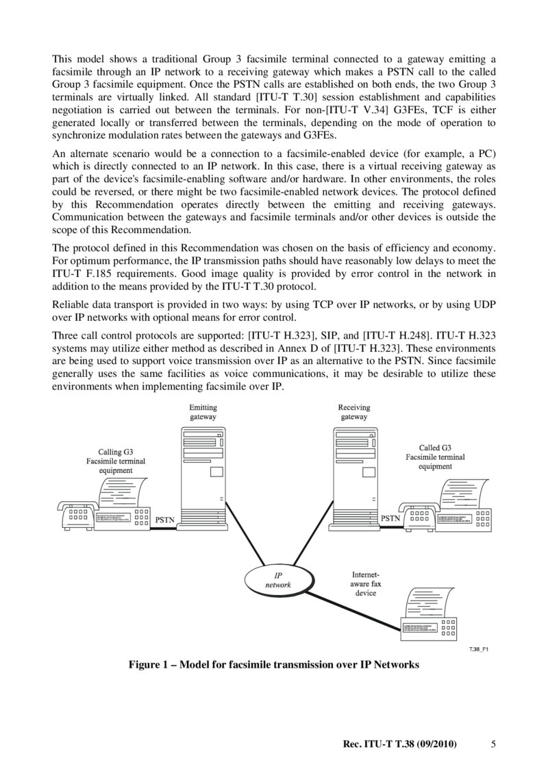
This model shows a traditional Group 3 facsimile terminal connected to a gateway emitting a facsimile through an IP network to a receiving gateway which makes a PSTN call to the called Group 3 facsimile equipment. Once the PSTN calls are established on both ends, the two Group 3 terminals are virtually linked. All standard [ITU-T T.30] session establishment and capabilities negotiation is carried out between the terminals. For non-[ITU-T V.34] G3FEs, TCF is either generated locally or transferred between the terminals, depending on the mode of operation to synchronize modulation rates between the gateways and G3FEs.
An alternate scenario would be a connection to a facsimile-enabled device (for example, a PC) which is directly connected to an IP network. In this case, there is a virtual receiving gateway as part of the device's facsimile-enabling software and/or hardware. In other environments, the roles could be reversed, or there might be two facsimile-enabled network devices. The protocol defined by this Recommendation operates directly between the emitting and receiving gateways.
Communication between the gateways and facsimile terminals and/or other devices is outside the scope of this Recommendation.
The protocol defined in this Recommendation was chosen on the basis of efficiency and economy.
For optimum performance, the IP transmission paths should have reasonably low delays to meet the ITU-T F.185 requirements. Good image quality is provided by error control in the network in addition to the means provided by the ITU-T T.30 protocol.
Reliable data transport is provided in two ways: by using TCP over IP networks, or by using UDP over IP networks with optional means for error control.
Three call control protocols are supported: [ITU-T H.323], SIP, and [ITU-T H.248]. ITU-T H.323 systems may utilize either method as described in Annex D of [ITU-T H.323]. These environments are being used to support voice transmission over IP as an alternative to the PSTN. Since facsimile generally uses the same facilities as voice communications, it may be desirable to utilize these environments when implementing facsimile over IP.
Figure 1 – Model for facsimile transmission over IP Networks Rec. ITU-T T.38 (09/2010) 5
Página 12 — T-REC-T.38-201009-IPDF-E-1
Under some circumstances, it may be necessary to make some adjustments to the procedures between the gateway and the Group 3 terminal. Any such adjustments should not go beyond those available in the ITU-T T.30 protocol. These adjustments are implementation-dependent.
The protocol defined in this Recommendation focuses on the interval where a network connection has been established between two peers (gateway or IAF) implementing the real-time facsimile document transfer over Internet protocol.
Management issues, such as directory services (converting PSTN numbers to IP addresses when required), network hunting, user authentication and CDR (call detail record) collection and network management (SNMP or others) are important but are not addressed in this Recommendation.
Standardization of these issues will allow the implementation of a network based on third-party management devices, including sharing such devices with other Internet gateways such as Internet telephony and video, remote access and e-mail.
In addition, user interface aspects, such as the way that the facsimile operator selects the PSTN number of the destination or identifies himself to the system (for security purposes) are also not in the scope of this Recommendation. However, it is reasonable to assume that the facsimile operator uses the Group 3 terminal equipment keypad (using DTMF signals) or the IAF keyboard to provide the gateway with the required information.
Some of these issues mentioned here are being addressed in other ITU-T Recommendations and IETF RFCs. Specifically, [ITU-T H.323]/[ITU-T H.225.0], [ITU-T H.248], and SIP and the gatekeeper/call agent Recommendations address some of the above-mentioned dependencies.
It is intended that all procedures in this Recommendation conform to the requirements of
[ITU-T F.185].
The main body of this Recommendation describes the protocol and communication procedures between the emitting gateway and the receiving gateway. Communication between the gateways and the calling and called G3FEs, as well as call control procedures, are described in Annexes B, D, E, and F.
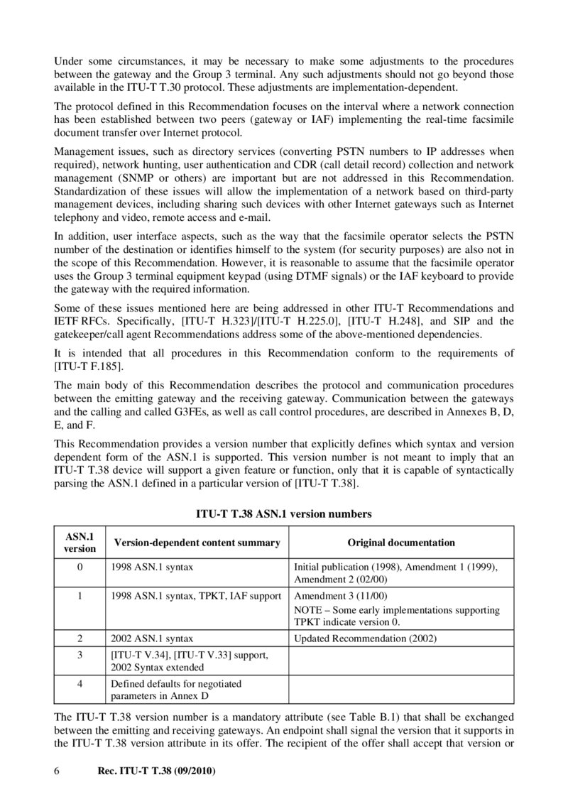
This Recommendation provides a version number that explicitly defines which syntax and version dependent form of the ASN.1 is supported. This version number is not meant to imply that an ITU-T T.38 device will support a given feature or function, only that it is capable of syntactically parsing the ASN.1 defined in a particular version of [ITU-T T.38].
ITU-T T.38 ASN.1 version numbers
ASN.1
version Version-dependent content summary Original documentation 0 1998 ASN.1 syntax Initial publication (1998), Amendment 1 (1999), Amendment 2 (02/00) 1 1998 ASN.1 syntax, TPKT, IAF support Amendment 3 (11/00) NOTE – Some early implementations supporting TPKT indicate version 0.
2 2002 ASN.1 syntax Updated Recommendation (2002) 3 [ITU-T V.34], [ITU-T V.33] support, 2002 Syntax extended 4 Defined defaults for negotiated parameters in Annex D The ITU-T T.38 version number is a mandatory attribute (see Table B.1) that shall be exchanged between the emitting and receiving gateways. An endpoint shall signal the version that it supports in the ITU-T T.38 version attribute in its offer. The recipient of the offer shall accept that version or 6 Rec. ITU-T T.38 (09/2010)
Página 13 — T-REC-T.38-201009-IPDF-E-1
modify the version attribute to be an equal or lower version when transmitting an answer to the initial offer. The recipient of an offer shall not respond with an answer containing a higher version than that which was offered.
Early implementations of ITU-T T.38 equipment may not provide an ITU-T T.38 version number.
In receipt of SDP without the version attribute, the endpoint shall assume that the version is 0.
Version 0 devices are recommended to explicitly advertise their version.
5.1 Conventions 5.1.1 SDP offer/answer protocol variants This Recommendation provides example signalling syntax. There are two models for the session description protocol (SDP) concerning the indication and negotiation of media and transport capabilities:
– the name "legacy SDP Offer/Answer" indicates SDP Offer/Answer, according to
[IETF RFC 3264];
– the name "revised SDP Offer/Answer" indicates SDP Offer/Answer, according to [IETF RFC 5939] and [b-IETF Draft MediaCapNeg].
6 Communication between gateways 6.1 Internet protocol – TCP or UDP The public Internet service provides two principal modes of data transmission:
– TCP (transmission control protocol) – A session-based, confirmed delivery service; – UDP (user datagram protocol) – Datagram service, non-confirmed delivery.
This Recommendation allows the use of either TCP or UDP depending on the service environment.
It defines a layered protocol such that the ITU-T T.38 messages exchanged for TCP and UDP implementations are identical.
6.2 Gateway facsimile data transfer functions The emitting gateway shall demodulate the ITU-T T.30 transmission received from the calling terminal. The ITU-T T.30 facsimile control and image data shall be transferred in an octet stream structure using the IFP packets, over a transport protocol (TCP or UDP). The following signals are not transferred between gateways but are generated or handled locally between the gateway and the G3FE: CNG, CED, and in one mode, TCF. The gateways may indicate the detection of the tonal signals CNG and CED so that the other gateway can generate them.
The receiving gateway shall decode the transferred information and establish communication with the called facsimile terminal using normal ITU-T T.30 procedures. The receiving gateway shall forward all relevant responses from the called terminal to the emitting gateway.
The facsimile data transfer structure is described in clause 7.1.3. The flow between gateways is described in clause 8.
6.2.1 Treatment of non-standard facilities requests The emitting gateway may optionally ignore NSF, NCS and NSS, take appropriate action or pass the information to the receiving gateway. The receiving gateway may optionally ignore NSF, NCS and NSS or take appropriate action, including passing the information to the receiving G3FE.
Information in other frames related directly to these frames may be altered by the gateway.
Rec. ITU-T T.38 (09/2010) 7
Página 14 — T-REC-T.38-201009-IPDF-E-1
7 IFT protocol definition and procedures 7.1 General This clause contains the textual description of the IFT protocol. The IFT protocol is specified by the ASN.1 description in Annex A. In the case of a conflict between the ASN.1 and the text, the ASN.1 governs. The ASN.1 encoding in Annex A should employ the BASIC-ALIGNED version of packed encoding rules (PER) according to [ITU-T X.691].
7.1.1 Bit and octet transmission order Transmission order is as defined in [IETF RFC 791] "Internet Protocol", quoted herein as reference:
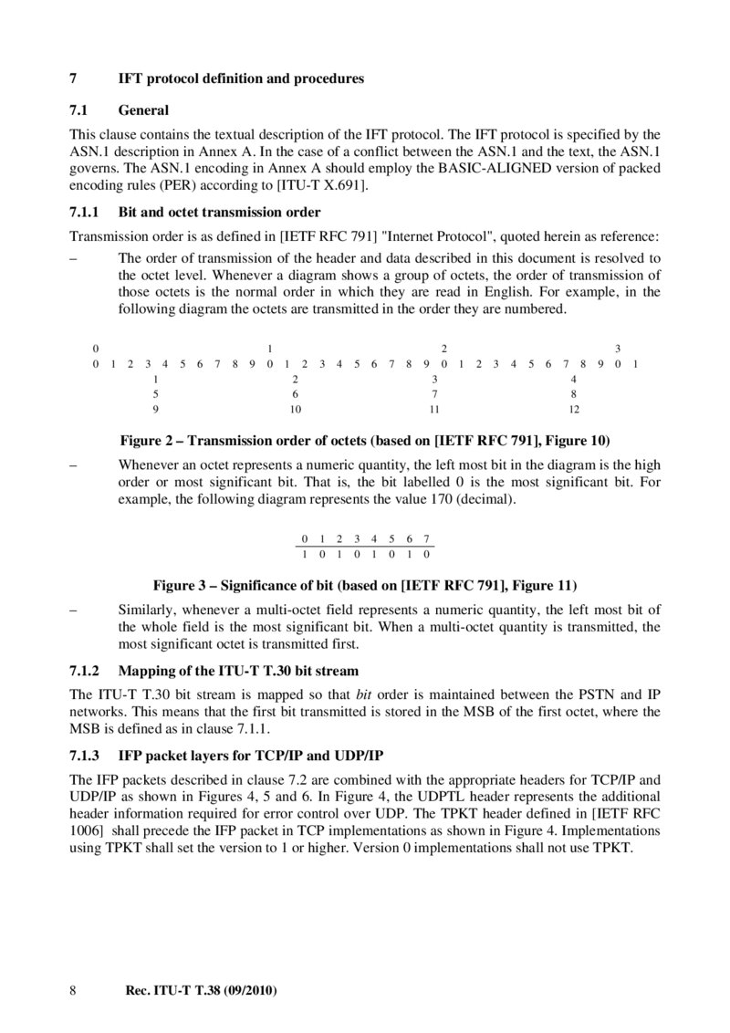
– The order of transmission of the header and data described in this document is resolved to the octet level. Whenever a diagram shows a group of octets, the order of transmission of those octets is the normal order in which they are read in English. For example, in the following diagram the octets are transmitted in the order they are numbered.
00 1 2 3 4 5 6 7 8 9 1 0 1 5 9 1 2 3 4 5 6 7 8 2 6 10 9 3 7 11 2 0 1 2 3 4 5 6 7 8 9 3 0 1 4 8 12 Figure 2 – Transmission order of octets (based on [IETF RFC 791], Figure 10) – Whenever an octet represents a numeric quantity, the left most bit in the diagram is the high order or most significant bit. That is, the bit labelled 0 is the most significant bit. For example, the following diagram represents the value 170 (decimal).
01 1 0 2 1 3 0 4 1 5 0 6 1 7 0 Figure 3 – Significance of bit (based on [IETF RFC 791], Figure 11) – Similarly, whenever a multi-octet field represents a numeric quantity, the left most bit of the whole field is the most significant bit. When a multi-octet quantity is transmitted, the most significant octet is transmitted first.
7.1.2 Mapping of the ITU-T T.30 bit stream The ITU-T T.30 bit stream is mapped so that bit order is maintained between the PSTN and IP networks. This means that the first bit transmitted is stored in the MSB of the first octet, where the MSB is defined as in clause 7.1.1.
7.1.3 IFP packet layers for TCP/IP and UDP/IP The IFP packets described in clause 7.2 are combined with the appropriate headers for TCP/IP and UDP/IP as shown in Figures 4, 5 and 6. In Figure 4, the UDPTL header represents the additional header information required for error control over UDP. The TPKT header defined in [IETF RFC 1006] shall precede the IFP packet in TCP implementations as shown in Figure 4. Implementations using TPKT shall set the version to 1 or higher. Version 0 implementations shall not use TPKT.
8 Rec. ITU-T T.38 (09/2010)
Página 15 — T-REC-T.38-201009-IPDF-E-1
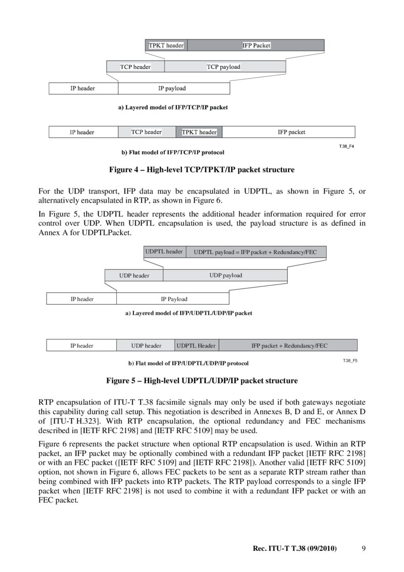
Figure 4 – High-level TCP/TPKT/IP packet structure For the UDP transport, IFP data may be encapsulated in UDPTL, as shown in Figure 5, or alternatively encapsulated in RTP, as shown in Figure 6.
In Figure 5, the UDPTL header represents the additional header information required for error control over UDP. When UDPTL encapsulation is used, the payload structure is as defined in Annex A for UDPTLPacket.
UDPTL header UDP payload UDP header IP header UDPTL payload = IFP packet + Redundancy/FEC IP Payload a) Layered model of IFP/UDPTL/UDP/IP packet IP header UDP header UDPTL Header IFP packet + Redundancy/FEC
T.38_F5
b) Flat model of IFP/UDPTL/UDP/IP protocol Figure 5 – High-level UDPTL/UDP/IP packet structure RTP encapsulation of ITU-T T.38 facsimile signals may only be used if both gateways negotiate this capability during call setup. This negotiation is described in Annexes B, D and E, or Annex D of [ITU-T H.323]. With RTP encapsulation, the optional redundancy and FEC mechanisms described in [IETF RFC 2198] and [IETF RFC 5109] may be used.
Figure 6 represents the packet structure when optional RTP encapsulation is used. Within an RTP packet, an IFP packet may be optionally combined with a redundant IFP packet [IETF RFC 2198] or with an FEC packet ([IETF RFC 5109] and [IETF RFC 2198]). Another valid [IETF RFC 5109] option, not shown in Figure 6, allows FEC packets to be sent as a separate RTP stream rather than being combined with IFP packets into RTP packets. The RTP payload corresponds to a single IFP packet when [IETF RFC 2198] is not used to combine it with a redundant IFP packet or with an FEC packet.
Rec. ITU-T T.38 (09/2010) 9
Página 16 — T-REC-T.38-201009-IPDF-E-1
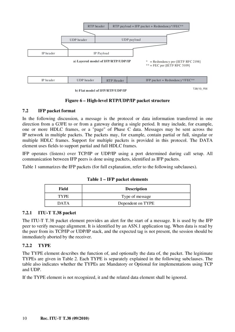
RTP header RTP payload = IFP packet + Redundancy*/FEC** UDP payload UDP header IP header IP Payload a) Layered model of IFP/RTP/UDP/IP IP header UDP header * = Redundancy per [IETF RFC 2198] ** = FEC per [IETF RFC 5109] IFP packet + Redundancy*/FEC** RTP Header b) Flat model of IFP/RTP/UDP/IP
T.38(10)_F06
Figure 6 – High-level RTP/UDP/IP packet structure 7.2 IFP packet format In the following discussion, a message is the protocol or data information transferred in one direction from a G3FE to or from a gateway during a single period. It may include, for example, one or more HDLC frames, or a "page" of Phase C data. Messages may be sent across the IP network in multiple packets. The packets may, for example, contain partial or full, singular or multiple HDLC frames. Support for multiple packets is provided in this protocol. The DATA element uses fields to support partial and full HDLC frames.
IFP operates (listens) over TCP/IP or UDP/IP using a port determined during call setup. All communication between IFP peers is done using packets, identified as IFP packets.
Table 1 summarizes the IFP packets (for full explanation, refer to the following subclauses).
Table 1 – IFP packet elements 7.2.1 Field Description
TYPE
Type of message
DATA
Dependent on TYPE ITU-T T.38 packet The ITU-T T.38 packet element provides an alert for the start of a message. It is used by the IFP peer to verify message alignment. It is identified by an ASN.1 application tag. When data is read by the peer from its TCP/IP or UDP/IP stack, and the expected tag is not present, the session should be immediately aborted by the receiver.
7.2.2
TYPE
The TYPE element describes the function of, and optionally the data of, the packet. The legitimate TYPEs are given in Table 2. Each TYPE is separately explained in the following subclauses. The table also indicates whether the TYPEs are Mandatory or Optional for implementations using TCP and UDP.
If the TYPE element is not recognized, it and the related data element shall be ignored.
10 Rec. ITU-T T.38 (09/2010)
Página 17 — T-REC-T.38-201009-IPDF-E-1
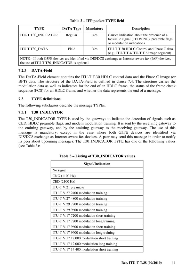
Table 2 – IFP packet TYPE field
TYPE
DATA Type Mandatory Description
ITU-T T30_INDICATOR
Regular Yes Carries indication about the presence of a facsimile signal (CED/CNG), preamble flags or modulation indications
ITU-T T30_DATA
Field Yes ITU-T T.30 HDLC Control and Phase C data (e.g., ITU-T T.4/ITU-T T.6 image segment) NOTE – If both G3FE devices are identified via DIS/DCS exchange as Internet-aware fax (IAF) devices, the use of ITU-T T30_INDICATOR is optional.
7.2.3 DATA-Field The DATA-Field element contains the ITU-T T.30 HDLC control data and the Phase C image (or BFT) data. The structure of the DATA-Field is defined in clause 7.4. The structure carries the modulation data as well as indicators for the end of an HDLC frame, the status of the frame check sequence (FCS) for an HDLC frame, and whether the data represents the end of a message.
7.3 TYPE definitions The following subclauses describe the message TYPEs.
7.3.1
T30_INDICATOR
The T30_INDICATOR TYPE is used by the gateways to indicate the detection of signals such as CED, HDLC preamble flags, and modem modulation training. It is sent by the receiving gateway to the emitting gateway, and by the emitting gateway to the receiving gateway. The use of this message is mandatory, except in the case where both G3FE devices are identified via DIS/DCS exchange as Internet-aware fax devices. A peer may send this message in order to notify its peer about upcoming messages. The T30_INDICATOR TYPE has one of the following values (see Table 3):
Table 3 – Listing of T30_INDICATOR values Signal/Indication No signal CNG (1100 Hz) CED (2100 Hz) ITU-T V.21 preamble ITU-T V.27 2400 modulation training ITU-T V.27 4800 modulation training ITU-T V.29 7200 modulation training ITU-T V.29 9600 modulation training ITU-T V.17 7200 modulation short training ITU-T V.17 7200 modulation long training ITU-T V.17 9600 modulation short training ITU-T V.17 9600 modulation long training ITU-T V.17 12 000 modulation short training ITU-T V.17 12 000 modulation long training ITU-T V.17 14 400 modulation short training Rec. ITU-T T.38 (09/2010) 11
Página 18 — T-REC-T.38-201009-IPDF-E-1
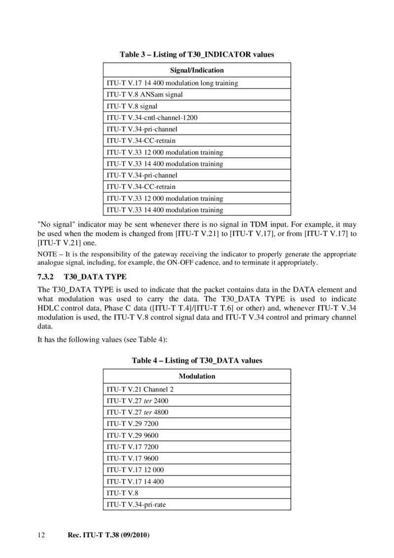
Table 3 – Listing of T30_INDICATOR values Signal/Indication ITU-T V.17 14 400 modulation long training ITU-T V.8 ANSam signal ITU-T V.8 signal ITU-T V.34-cntl-channel-1200 ITU-T V.34-pri-channel ITU-T V.34-CC-retrain ITU-T V.33 12 000 modulation training ITU-T V.33 14 400 modulation training ITU-T V.34-pri-channel ITU-T V.34-CC-retrain ITU-T V.33 12 000 modulation training ITU-T V.33 14 400 modulation training "No signal" indicator may be sent whenever there is no signal in TDM input. For example, it may be used when the modem is changed from [ITU-T V.21] to [ITU-T V.17], or from [ITU-T V.17] to [ITU-T V.21] one.
NOTE – It is the responsibility of the gateway receiving the indicator to properly generate the appropriate analogue signal, including, for example, the ON-OFF cadence, and to terminate it appropriately.
7.3.2
T30_DATA TYPE
The T30_DATA TYPE is used to indicate that the packet contains data in the DATA element and what modulation was used to carry the data. The T30_DATA TYPE is used to indicate HDLC control data, Phase C data ([ITU-T T.4]/[ITU-T T.6] or other) and, whenever ITU-T V.34 modulation is used, the ITU-T V.8 control signal data and ITU-T V.34 control and primary channel data.
It has the following values (see Table 4):
Table 4 – Listing of T30_DATA values Modulation ITU-T V.21 Channel 2 ITU-T V.27 ter 2400 ITU-T V.27 ter 4800
ITU-T V.29 7200
ITU-T V.29 9600
ITU-T V.17 7200
ITU-T V.17 9600
ITU-T V.17 12 000
ITU-T V.17 14 400
ITU-T V.8
ITU-T V.34-pri-rate 12 Rec. ITU-T T.38 (09/2010)
Página 19 — T-REC-T.38-201009-IPDF-E-1
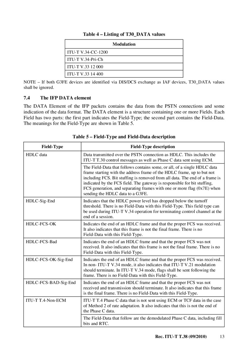
Table 4 – Listing of T30_DATA values Modulation
ITU-T V.34-CC-1200
ITU-T V.34-Pri-Ch
ITU-T V.33 12 000
ITU-T V.33 14 400
NOTE – If both G3FE devices are identified via DIS/DCS exchange as IAF devices, T30_DATA values shall be ignored.
7.4 The IFP DATA element The DATA Element of the IFP packets contains the data from the PSTN connections and some indication of the data format. The DATA element is a structure containing one or more Fields. Each Field has two parts: the first part indicates the Field-Type; the second part contains the Field-Data.
The meanings for the Field-Type are shown in Table 5.
Table 5 – Field-Type and Field-Data description Field-Type HDLC data Field-Type description Data transmitted over the PSTN connection as HDLC. This includes the ITU-T T.30 control messages as well as Phase C data sent using ECM.
The Field-Data that follows contains some, or all, of a single HDLC data frame starting with the address frame of the HDLC frame, up to but not including FCS. Bit stuffing is removed from all data. The end of a frame is indicated by the FCS field. The gateway is responsible for bit stuffing, FCS generation, and separating frames with one or more flag (0x7E) when sending the HDLC data to a G3FE.
HDLC-Sig-End Indicates that the HDLC power level has dropped below the turnoff threshold. There is no Field-Data with this Field-Type. This field type can be used during ITU-T V.34 operation for terminating control channel at the end of a session.
HDLC-FCS-OK
Indicates the end of an HDLC frame and that the proper FCS was received.
It also indicates that this frame is not the final frame. There is no Field-Data with this Field-Type.
HDLC-FCS-Bad Indicates the end of an HDLC frame and that the proper FCS was not received. It also indicates that this frame is not the final frame. There is no Field-Data with this Field-Type.
HDLC-FCS-OK-Sig-End Indicates the end of an HDLC frame and that the proper FCS was received.
In non- ITU-T V.34 mode, it also indicates that ITU-T V.21 modulation should terminate. In ITU-T V.34 mode, flags shall be sent following the frame. There is no Field-Data with this Field-Type.
HDLC-FCS-BAD-Sig-End Indicates the end of an HDLC frame and that the proper FCS was not received and transmission should terminate. It also indicates that this frame is the final frame. There is no Field-Data with this Field-Type.
ITU-T T.4-Non-ECM ITU-T T.4 Phase C data that is not sent using ECM or TCF data in the case of Method 2 of rate adaptation. It also indicates that this is not the end of the Phase C data.
The Field-Data that follow are the demodulated Phase C data, including fill bits and RTC.
Rec. ITU-T T.38 (09/2010) 13
Página 20 — T-REC-T.38-201009-IPDF-E-1
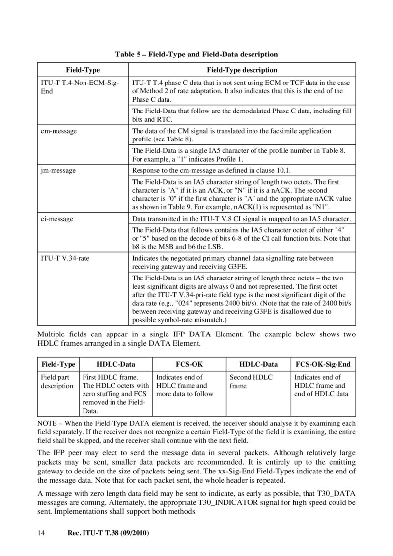
Table 5 – Field-Type and Field-Data description Field-Type Field-Type description ITU-T T.4-Non-ECM-SigEnd ITU-T T.4 phase C data that is not sent using ECM or TCF data in the case of Method 2 of rate adaptation. It also indicates that this is the end of the Phase C data.
The Field-Data that follow are the demodulated Phase C data, including fill bits and RTC.
cm-message The data of the CM signal is translated into the facsimile application profile (see Table 8).
The Field-Data is a single IA5 character of the profile number in Table 8.
For example, a "1" indicates Profile 1. jm-message Response to the cm-message as defined in clause 10.1.
The Field-Data is an IA5 character string of length two octets. The first character is "A" if it is an ACK, or "N" if it is a nACK. The second character is "0" if the first character is "A" and the appropriate nACK value as shown in Table 9. For example, nACK(1) is represented as "N1".
ci-message Data transmitted in the ITU-T V.8 CI signal is mapped to an IA5 character.
The Field-Data that follows contains the IA5 character octet of either "4" or "5" based on the decode of bits 6-8 of the CI call function bits. Note that b8 is the MSB and b6 the LSB.
ITU-T V.34-rate Indicates the negotiated primary channel data signalling rate between receiving gateway and receiving G3FE.
The Field-Data is an IA5 character string of length three octets – the two least significant digits are always 0 and not represented. The first octet after the ITU-T V.34-pri-rate field type is the most significant digit of the data rate (e.g., "024" represents 2400 bit/s). (Note that the rate of 2400 bit/s between receiving gateway and receiving G3FE is disallowed due to possible symbol-rate mismatch.) Multiple fields can appear in a single IFP DATA Element. The example below shows two HDLC frames arranged in a single DATA Element.
Field-Type Field part description HDLC-Data
FCS-OK
First HDLC frame. Indicates end of The HDLC octets with HDLC frame and zero stuffing and FCS more data to follow removed in the FieldData.
HDLC-Data FCS-OK-Sig-End Second HDLC frame Indicates end of HDLC frame and end of HDLC data NOTE – When the Field-Type DATA element is received, the receiver should analyse it by examining each field separately. If the receiver does not recognize a certain Field-Type of the field it is examining, the entire field shall be skipped, and the receiver shall continue with the next field.
The IFP peer may elect to send the message data in several packets. Although relatively large packets may be sent, smaller data packets are recommended. It is entirely up to the emitting gateway to decide on the size of packets being sent. The xx-Sig-End Field-Types indicate the end of the message data. Note that for each packet sent, the whole header is repeated.
A message with zero length data field may be sent to indicate, as early as possible, that T30_DATA messages are coming. Alternately, the appropriate T30_INDICATOR signal for high speed could be sent. Implementations shall support both methods.
14 Rec. ITU-T T.38 (09/2010)
Página 21 — T-REC-T.38-201009-IPDF-E-1
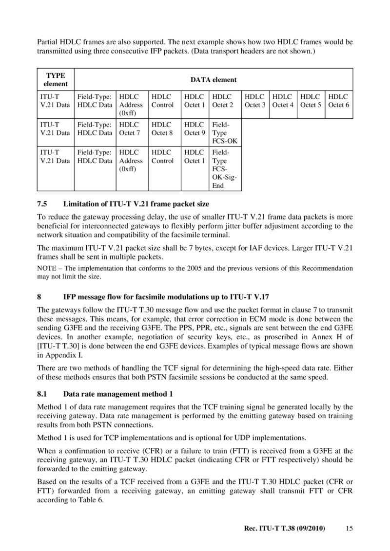
Partial HDLC frames are also supported. The next example shows how two HDLC frames would be transmitted using three consecutive IFP packets. (Data transport headers are not shown.)
TYPE
element DATA element
ITU-T
V.21 Data Field-Type: HDLC HDLC Data Address (0xff)
HDLC
Control
HDLC HDLC
Octet 1 Octet 2
ITU-T
V.21 Data Field-Type: HDLC HDLC Data Octet 7
HDLC
Octet 8 HDLC FieldOctet 9 Type
FCS-OK
ITU-T
V.21 Data Field-Type: HDLC HDLC Data Address (0xff)
HDLC
Control HDLC FieldOctet 1 Type FCSOK-SigEnd 7.5
HDLC HDLC HDLC HDLC
Octet 3 Octet 4 Octet 5 Octet 6 Limitation of ITU-T V.21 frame packet size To reduce the gateway processing delay, the use of smaller ITU-T V.21 frame data packets is more beneficial for interconnected gateways to flexibly perform jitter buffer adjustment according to the network situation and compatibility of the facsimile terminal.
The maximum ITU-T V.21 packet size shall be 7 bytes, except for IAF devices. Larger ITU-T V.21 frames shall be sent in multiple packets.
NOTE – The implementation that conforms to the 2005 and the previous versions of this Recommendation may not limit the size.
8 IFP message flow for facsimile modulations up to ITU-T V.17 The gateways follow the ITU-T T.30 message flow and use the packet format in clause 7 to transmit these messages. This means, for example, that error correction in ECM mode is done between the sending G3FE and the receiving G3FE. The PPS, PPR, etc., signals are sent between the end G3FE devices. In another example, negotiation of security keys, etc., as proscribed in Annex H of [ITU-T T.30] is done between the end G3FE devices. Examples of typical message flows are shown in Appendix I.
There are two methods of handling the TCF signal for determining the high-speed data rate. Either of these methods ensures that both PSTN facsimile sessions be conducted at the same speed.
8.1 Data rate management method 1 Method 1 of data rate management requires that the TCF training signal be generated locally by the receiving gateway. Data rate management is performed by the emitting gateway based on training results from both PSTN connections.
Method 1 is used for TCP implementations and is optional for UDP implementations.
When a confirmation to receive (CFR) or a failure to train (FTT) is received from a G3FE at the receiving gateway, an ITU-T T.30 HDLC packet (indicating CFR or FTT respectively) should be forwarded to the emitting gateway.
Based on the results of a TCF received from a G3FE and the ITU-T T.30 HDLC packet (CFR or FTT) forwarded from a receiving gateway, an emitting gateway shall transmit FTT or CFR according to Table 6.
Rec. ITU-T T.38 (09/2010) 15
Página 22 — T-REC-T.38-201009-IPDF-E-1
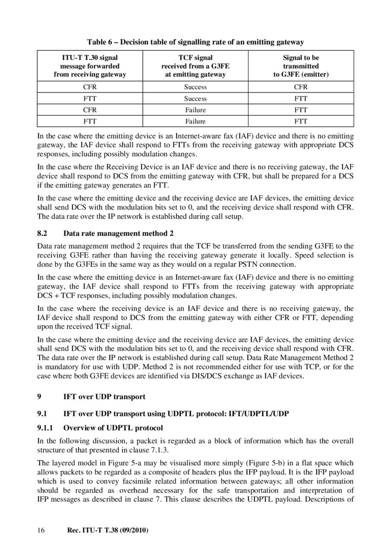
Table 6 – Decision table of signalling rate of an emitting gateway ITU-T T.30 signal message forwarded from receiving gateway TCF signal received from a G3FE at emitting gateway Signal to be transmitted to G3FE (emitter) CFR Success CFR FTT Success FTT CFR Failure FTT FTT Failure FTT In the case where the emitting device is an Internet-aware fax (IAF) device and there is no emitting gateway, the IAF device shall respond to FTTs from the receiving gateway with appropriate DCS responses, including possibly modulation changes.
In the case where the Receiving Device is an IAF device and there is no receiving gateway, the IAF device shall respond to DCS from the emitting gateway with CFR, but shall be prepared for a DCS if the emitting gateway generates an FTT.
In the case where the emitting device and the receiving device are IAF devices, the emitting device shall send DCS with the modulation bits set to 0, and the receiving device shall respond with CFR.
The data rate over the IP network is established during call setup.
8.2 Data rate management method 2 Data rate management method 2 requires that the TCF be transferred from the sending G3FE to the receiving G3FE rather than having the receiving gateway generate it locally. Speed selection is done by the G3FEs in the same way as they would on a regular PSTN connection.
In the case where the emitting device is an Internet-aware fax (IAF) device and there is no emitting gateway, the IAF device shall respond to FTTs from the receiving gateway with appropriate DCS + TCF responses, including possibly modulation changes.
In the case where the receiving device is an IAF device and there is no receiving gateway, the IAF device shall respond to DCS from the emitting gateway with either CFR or FTT, depending upon the received TCF signal.
In the case where the emitting device and the receiving device are IAF devices, the emitting device shall send DCS with the modulation bits set to 0, and the receiving device shall respond with CFR.
The data rate over the IP network is established during call setup. Data Rate Management Method 2 is mandatory for use with UDP. Method 2 is not recommended either for use with TCP, or for the case where both G3FE devices are identified via DIS/DCS exchange as IAF devices.
9 IFT over UDP transport 9.1 IFT over UDP transport using UDPTL protocol: IFT/UDPTL/UDP 9.1.1 Overview of UDPTL protocol In the following discussion, a packet is regarded as a block of information which has the overall structure of that presented in clause 7.1.3.
The layered model in Figure 5-a may be visualised more simply (Figure 5-b) in a flat space which allows packets to be regarded as a composite of headers plus the IFP payload. It is the IFP payload which is used to convey facsimile related information between gateways; all other information should be regarded as overhead necessary for the safe transportation and interpretation of IFP messages as described in clause 7. This clause describes the UDPTL payload. Descriptions of 16 Rec. ITU-T T.38 (09/2010)
Página 23 — T-REC-T.38-201009-IPDF-E-1
the IP and UDP headers and payloads are found in [IETF RFC 791] and [IETF RFC 768], respectively.
UDPTL packets comprise a sequence number and a variable length, octet aligned, payload.
UDPTL packets are based upon the principle of framing. Each packet may contain one or more IFP packets in its payload section. The first packet in any payload is always formatted in accordance with the specifications of clause 7, and must correspond to the sequence number supplied in the header (for instance, the first field in a payload with sequence number 15 must have been generated 5 payloads later than the first field in the payload with sequence number 10). The IFP packet in a UDPTL payload is referred to as the "primary". Additional fields may be included in a payload after the primary. These fields are referred to as "secondaries" and may or may not be formatted as per clause 7 specifications depending on their form.
9.1.2 UDPTL header section format The UDPTL sequence number is used to identify the sequencing in a payload.
9.1.2.1 UDPTL sequence number element Each packet, and therefore primary field, has its own corresponding unique sequence number which specifies an ordering at the receiving gateway should packets arrive out of sequence. To enable gateways to be synchronized upon receipt of any packet, the first primary field transmitted shall have sequence number zero. Successive primaries shall have linearly increasing (integer adjacent) sequence numbers.
9.1.3 UDPTL payload section format During ITU-T H.323 capabilities exchange, a gateway shall indicate its support of the available error protection schemes, parity FEC, or redundancy. Based on these capabilities, a choice may be made on which scheme is used for error protection. If a capability is indicated to receive both parity error correction frames and redundant frames, then either scheme may be used. If, however, a gateway indicates a capability to receive only redundant error protection frames, then the transmitting gateway may not send parity FEC frames. The support of parity FEC is optional; a gateway providing parity FEC receive services should, however, also be capable of receiving redundant messages. A gateway may choose not to send any error correction messages.
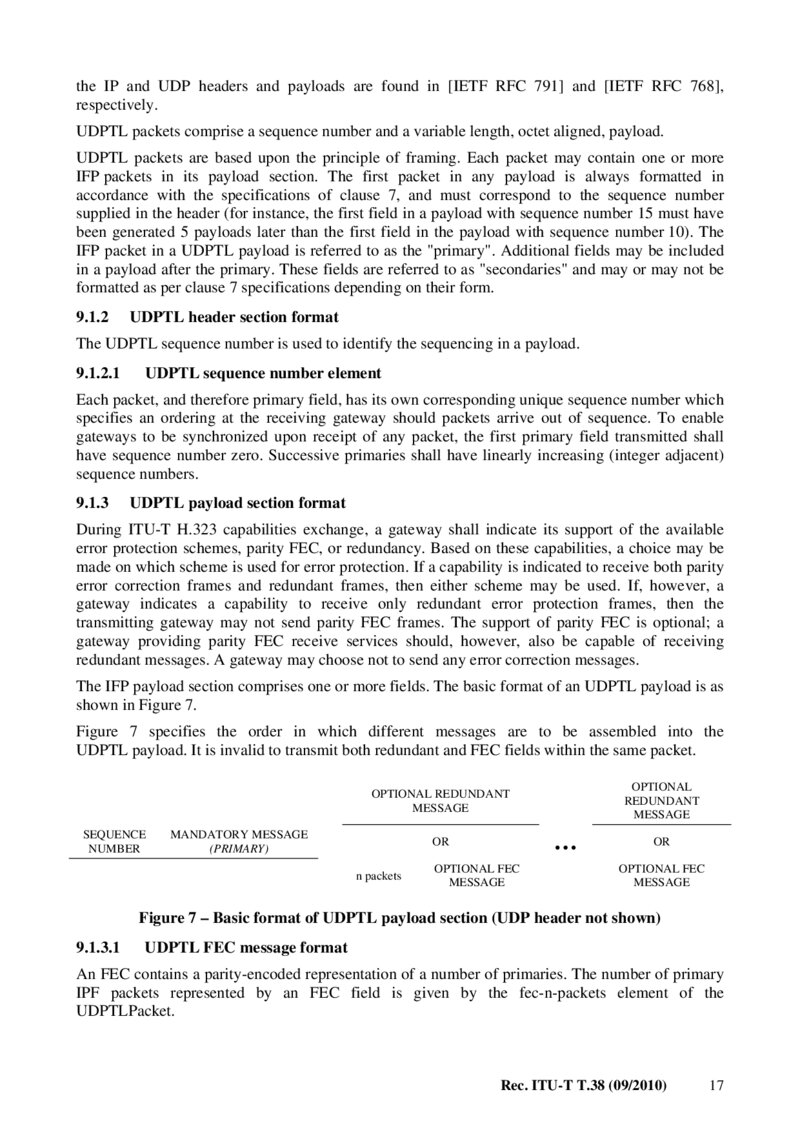
The IFP payload section comprises one or more fields. The basic format of an UDPTL payload is as shown in Figure 7.
Figure 7 specifies the order in which different messages are to be assembled into the UDPTL payload. It is invalid to transmit both redundant and FEC fields within the same packet.
OPTIONAL
REDUNDANT
MESSAGE
OPTIONAL REDUNDANT
MESSAGE
SEQUENCE
NUMBER
MANDATORY MESSAGE
(PRIMARY)
… OR n packets
OPTIONAL FEC
MESSAGE
OR
OPTIONAL FEC
MESSAGE
Figure 7 – Basic format of UDPTL payload section (UDP header not shown) 9.1.3.1 UDPTL FEC message format An FEC contains a parity-encoded representation of a number of primaries. The number of primary IPF packets represented by an FEC field is given by the fec-n-packets element of the UDPTLPacket.
Rec. ITU-T T.38 (09/2010) 17
Página 24 — T-REC-T.38-201009-IPDF-E-1
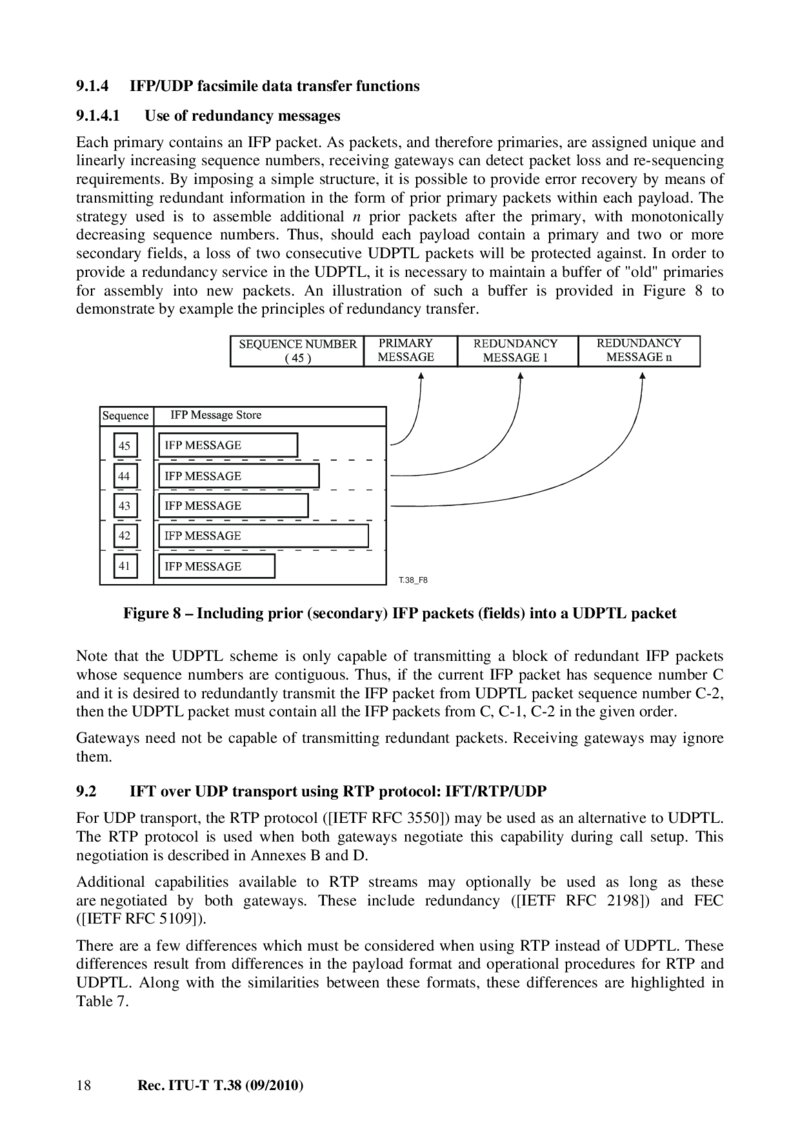
9.1.4 IFP/UDP facsimile data transfer functions 9.1.4.1 Use of redundancy messages Each primary contains an IFP packet. As packets, and therefore primaries, are assigned unique and linearly increasing sequence numbers, receiving gateways can detect packet loss and re-sequencing requirements. By imposing a simple structure, it is possible to provide error recovery by means of transmitting redundant information in the form of prior primary packets within each payload. The strategy used is to assemble additional n prior packets after the primary, with monotonically decreasing sequence numbers. Thus, should each payload contain a primary and two or more secondary fields, a loss of two consecutive UDPTL packets will be protected against. In order to provide a redundancy service in the UDPTL, it is necessary to maintain a buffer of "old" primaries for assembly into new packets. An illustration of such a buffer is provided in Figure 8 to demonstrate by example the principles of redundancy transfer.
45 44 43 42 41
T.38_F8
Figure 8 – Including prior (secondary) IFP packets (fields) into a UDPTL packet Note that the UDPTL scheme is only capable of transmitting a block of redundant IFP packets whose sequence numbers are contiguous. Thus, if the current IFP packet has sequence number C and it is desired to redundantly transmit the IFP packet from UDPTL packet sequence number C-2, then the UDPTL packet must contain all the IFP packets from C, C-1, C-2 in the given order.
Gateways need not be capable of transmitting redundant packets. Receiving gateways may ignore them.
9.2 IFT over UDP transport using RTP protocol: IFT/RTP/UDP For UDP transport, the RTP protocol ([IETF RFC 3550]) may be used as an alternative to UDPTL.
The RTP protocol is used when both gateways negotiate this capability during call setup. This negotiation is described in Annexes B and D.
Additional capabilities available to RTP streams may optionally be used as long as these are negotiated by both gateways. These include redundancy ([IETF RFC 2198]) and FEC
([IETF RFC 5109]).
There are a few differences which must be considered when using RTP instead of UDPTL. These differences result from differences in the payload format and operational procedures for RTP and UDPTL. Along with the similarities between these formats, these differences are highlighted in Table 7.
18 Rec. ITU-T T.38 (09/2010)
Página 25 — T-REC-T.38-201009-IPDF-E-1
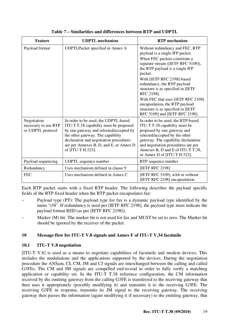
Table 7 – Similarities and differences between RTP and UDPTL Feature UDPTL mechanism RTP mechanism Payload format UDPTLPacket specified in Annex A Without redundancy and FEC, RTP payload is a single IFP packet.
When FEC packets constitute a separate stream ([IETF RFC 5109]), the RTP payload is a single IFP packet.
With [IETF RFC 2198]-based redundancy, the RTP payload structure is as specified in [IETF
RFC 2198].
With FEC that uses [IETF RFC 2198] encapsulation, the RTP payload structure is as specified in [IETF RFC 5109] and [IETF RFC 2198].
Negotiation necessary to use RTP or UDPTL protocol In order to be used, the UDPTL-based ITU-T T.38 capability must be proposed by one gateway and selected/accepted by the other gateway. The capability declaration and negotiation procedures are per Annexes B, D, and E, or Annex D of [ITU-T H.323].
In order to be used, the RTP-based ITU-T T.38 capability must be proposed by one gateway and selected/accepted by the other gateway. The capability declaration and negotiation procedures are per Annexes B, D and E of ITU-T T.38, or Annex D of [ITU-T H.323].
Payload sequencing UDPTL sequence number RTP sequence number Redundancy Uses mechanism defined in clause 9
[IETF RFC 2198]
FEC Uses mechanism defined in Annex C [IETF RFC 5109], with or without [IETF RFC 2198] encapsulation Each RTP packet starts with a fixed RTP header. The following describes the payload specific fields of the RTP fixed header when the RTP packet encapsulates fax:
– Payload type (PT): The payload type for fax is a dynamic payload type identified by the name "t38". If redundancy is used per [IETF RFC 2198], the payload type must indicate the payload format RED (as per [IETF RFC 2198]).
– Marker (M) bit: The marker bit is not used for fax and MUST be set to zero. The Marker bit should be ignored by the receiver of the packet.
10 Message flow for ITU-T V.8 signals and Annex F of ITU-T V.34 facsimile 10.1 ITU-T V.8 negotiation [ITU-T V.8] is used as a means to negotiate capabilities of facsimile and modem devices. This includes the modulations and the applications supported by the devices. During the negotiation procedure the ANSam, CI, CM, JM and CJ signals are interchanged between the calling and called G3FEs. The CM and JM signals are compelled end-to-end in order to fully verify a matching application or capability set. In the ITU-T T.38 reference configuration, the CM information received by the emitting gateway from the calling G3FE is transferred to the receiving gateway that then uses it appropriately (possibly modifying it) and transmits it to the receiving G3FE. The receiving G3FE in response, transmits its JM signal to the receiving gateway. The receiving gateway then passes the information (again modifying it if necessary) to the emitting gateway, that Rec. ITU-T T.38 (09/2010) 19
Página 26 — T-REC-T.38-201009-IPDF-E-1
in turn, transmits it to the calling G3FE. Once the emitting gateway has the JM information, it has full knowledge of the connection capabilities.
At the initiation of a call, the ANSam signal begins the ITU-T V.8 exchange for both ITU-T V.34 facsimile and ITU-T V.8-based modems. Call initiation in a multimode gateway, including ITU-T V.8-based modems and ITU-T V.34 G3FEs, is described in Annex F.
This clause describes the handling of ANSam and the ITU-T V.8 exchange for call initiation in facsimile-only gateways as well as for supporting ITU-T V.34 turn-around polling (see clause 10.3.5) and re-starting ITU-T V.34 in manual mode (see clause 10.3.6).
ANSam shall be detected by the receiving gateway and generated by the emitting gateway. When ANSam is detected by the receiving gateway, it shall be reported using the v8-ansam indicator if the emitting gateway is ITU-T V.34 capable. If the emitting gateway is not ITU-T V.34 capable, the receiving gateway shall report ANSam using the ced t30-indicator.
In the event that there is a timeout in response to an ANSam generated by the emitting gateway, resulting in an ITU-T V.21 response, either gateway may elect to prevent a possible return to ITU-T V.8 negotiations by resetting the ITU-T V.8 bit of the DIS message (bit 6, first octet).
An emitting gateway shall report the facsimile application profile (FAP) to the receiving gateway when it has detected two identical/consecutive CM signals, and has verified that the call function category octet contains a facsimile function. If the call function is not a valid facsimile value, then the call can be terminated as being a non-supported call type. The profile is transmitted to the receiving gateway using the cm-message data Field-Type, where it is regenerated for transmission to the receiving G3FE.
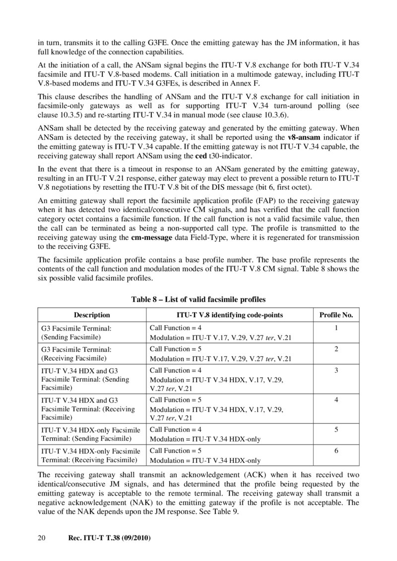
The facsimile application profile contains a base profile number. The base profile represents the contents of the call function and modulation modes of the ITU-T V.8 CM signal. Table 8 shows the six possible valid facsimile profiles.
Table 8 – List of valid facsimile profiles Description ITU-T V.8 identifying code-points Profile No.
G3 Facsimile Terminal: (Sending Facsimile) Call Function = 4 Modulation = ITU-T V.17, V.29, V.27 ter, V.21 1 G3 Facsimile Terminal:
(Receiving Facsimile) Call Function = 5 Modulation = ITU-T V.17, V.29, V.27 ter, V.21 2 ITU-T V.34 HDX and G3 Facsimile Terminal: (Sending Facsimile) Call Function = 4 Modulation = ITU-T V.34 HDX, V.17, V.29, V.27 ter, V.21 3 ITU-T V.34 HDX and G3 Facsimile Terminal: (Receiving Facsimile) Call Function = 5 Modulation = ITU-T V.34 HDX, V.17, V.29, V.27 ter, V.21 4 ITU-T V.34 HDX-only Facsimile Terminal: (Sending Facsimile) Call Function = 4 Modulation = ITU-T V.34 HDX-only 5 ITU-T V.34 HDX-only Facsimile Terminal: (Receiving Facsimile) Call Function = 5 Modulation = ITU-T V.34 HDX-only 6 The receiving gateway shall transmit an acknowledgement (ACK) when it has received two identical/consecutive JM signals, and has determined that the profile being requested by the emitting gateway is acceptable to the remote terminal. The receiving gateway shall transmit a negative acknowledgement (NAK) to the emitting gateway if the profile is not acceptable. The value of the NAK depends upon the JM response. See Table 9.
20 Rec. ITU-T T.38 (09/2010)
Página 27 — T-REC-T.38-201009-IPDF-E-1
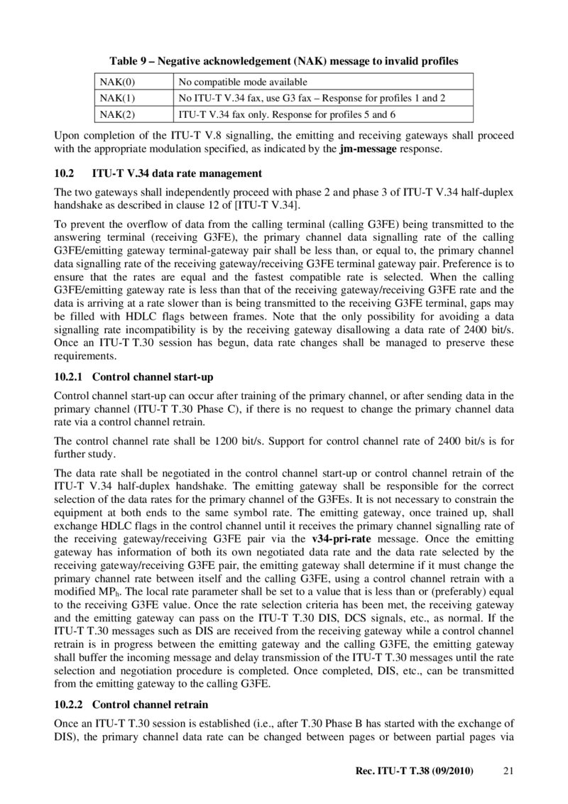
Table 9 – Negative acknowledgement (NAK) message to invalid profiles
NAK(0)
No compatible mode available
NAK(1)
No ITU-T V.34 fax, use G3 fax – Response for profiles 1 and 2
NAK(2)
ITU-T V.34 fax only. Response for profiles 5 and 6 Upon completion of the ITU-T V.8 signalling, the emitting and receiving gateways shall proceed with the appropriate modulation specified, as indicated by the jm-message response.
10.2 ITU-T V.34 data rate management The two gateways shall independently proceed with phase 2 and phase 3 of ITU-T V.34 half-duplex handshake as described in clause 12 of [ITU-T V.34].
To prevent the overflow of data from the calling terminal (calling G3FE) being transmitted to the answering terminal (receiving G3FE), the primary channel data signalling rate of the calling G3FE/emitting gateway terminal-gateway pair shall be less than, or equal to, the primary channel data signalling rate of the receiving gateway/receiving G3FE terminal gateway pair. Preference is to ensure that the rates are equal and the fastest compatible rate is selected. When the calling G3FE/emitting gateway rate is less than that of the receiving gateway/receiving G3FE rate and the data is arriving at a rate slower than is being transmitted to the receiving G3FE terminal, gaps may be filled with HDLC flags between frames. Note that the only possibility for avoiding a data signalling rate incompatibility is by the receiving gateway disallowing a data rate of 2400 bit/s.
Once an ITU-T T.30 session has begun, data rate changes shall be managed to preserve these requirements.
10.2.1 Control channel start-up Control channel start-up can occur after training of the primary channel, or after sending data in the primary channel (ITU-T T.30 Phase C), if there is no request to change the primary channel data rate via a control channel retrain.
The control channel rate shall be 1200 bit/s. Support for control channel rate of 2400 bit/s is for further study.
The data rate shall be negotiated in the control channel start-up or control channel retrain of the ITU-T V.34 half-duplex handshake. The emitting gateway shall be responsible for the correct selection of the data rates for the primary channel of the G3FEs. It is not necessary to constrain the equipment at both ends to the same symbol rate. The emitting gateway, once trained up, shall exchange HDLC flags in the control channel until it receives the primary channel signalling rate of the receiving gateway/receiving G3FE pair via the v34-pri-rate message. Once the emitting gateway has information of both its own negotiated data rate and the data rate selected by the receiving gateway/receiving G3FE pair, the emitting gateway shall determine if it must change the primary channel rate between itself and the calling G3FE, using a control channel retrain with a modified MPh. The local rate parameter shall be set to a value that is less than or (preferably) equal to the receiving G3FE value. Once the rate selection criteria has been met, the receiving gateway and the emitting gateway can pass on the ITU-T T.30 DIS, DCS signals, etc., as normal. If the ITU-T T.30 messages such as DIS are received from the receiving gateway while a control channel retrain is in progress between the emitting gateway and the calling G3FE, the emitting gateway shall buffer the incoming message and delay transmission of the ITU-T T.30 messages until the rate selection and negotiation procedure is completed. Once completed, DIS, etc., can be transmitted from the emitting gateway to the calling G3FE.
10.2.2 Control channel retrain Once an ITU-T T.30 session is established (i.e., after T.30 Phase B has started with the exchange of DIS), the primary channel data rate can be changed between pages or between partial pages via Rec. ITU-T T.38 (09/2010) 21
Página 28 — T-REC-T.38-201009-IPDF-E-1
control channel retrain. Either the sending G3FE or the receiving G3FE can initiate a data rate change by sending AC. A control channel retrain from the G3FEs can be signalled using the v34CC-retrain indicator. A gateway may initiate a retrain sequence at an appropriate time in response to this indicator. The retrain sequence can cause an MPh exchange between a gateway and a G3FE, resulting in a new data signalling rate for the primary channel.
When a control channel retrain occurs in an attempt to change the primary channel data rate, the requirement to prevent data overflow, as defined in clause 10.2, shall be preserved. Either the calling G3FE or the receiving G3FE may initiate a data rate change request, leading to two main cases to consider. For each case, the rate may increase or decrease. The behaviour for each case is defined below:
Retrain initiated by the calling G3FE In this case, no signals are sent from the emitting gateway to the receiving gateway.
a) The calling G3FE requests a rate increase.
If the rate request would result in the calling G3FE rate to be greater than the rate between the receiving gateway and the receiving G3FE, the emitting gateway shall not allow the rate increase, else it may allow it.
b) The calling G3FE requests a rate decrease.
The emitting gateway may change the rate as requested.
Retrain initiated by the receiving G3FE In this case, the receiving gateway shall send the v34-CC-retrain indicator, followed by the v34-pri-rate message with the new data rate that is selected.
a) The receiving G3FE requests a rate increase.
The receiving gateway may change the rate as requested. The emitting gateway may, at an appropriate time, initiate a control-channel retrain with the sending G3FE, and increase the data rate of the calling G3FE if it is less than or equal to the new rate of the receiving G3FE.
b) The receiving G3FE requests a rate decrease.
The receiving gateway may change the rate as requested. If the new rate indicated by the v34-pri-rate message is less than the calling G3FE rate, the emitting gateway shall, at the appropriate time, initiate a control-channel retrain with the sending G3FE and decrease the primary channel data rate of the calling G3FE so that it is less than or equal to the new rate of the receiving G3FE.
Note that a control channel retrain may be initiated at any time when the control channel is active. One appropriate time for the emitting gateway to initiate the required retrain is after the post-page message exchange but before the start-up of the primary channel.
10.3 Facsimile mode 10.3.1 Control channel Control channel data exchange begins after the MPh exchanges are complete and the parameters for the control channel rate and the primary channel rate have been agreed.
The control channel is a full duplex channel that, unlike the non-ITU-T V.34 fax modes, sends flags in the absence of data (compared to silence for the non-ITU-T V.34 modes). It is the responsibility of the gateway or IAF to generate flags as needed during control channel operations.
Control channel packets are sent using v34-CC-1200 t30-data "modulation" value with Field-Types of hdlc-xxx.
22 Rec. ITU-T T.38 (09/2010)
Página 29 — T-REC-T.38-201009-IPDF-E-1
The hdlc-xxx-sig-end Field-Types indicate the end of an HDLC message. Flags shall be sent after this instead of "silence" as in non-ITU-T V.34 operation.
10.3.2 Switch from control channel to primary channel The source terminal indicates its intention to shut down the control channel and switch to the primary channel by sending continuous ONEs of at least 40 in number and until it detects that the recipient terminal has stopped sending flags.
An emitting gateway shall signal a receiving gateway or IAF that it is ready to transition to the primary channel by sending the v34-primary-channel indicator.
10.3.3 Primary channel Annex F of [ITU-T T.30] requires that all image data be sent using ECM. This means that primary channel data shall be sent in packets using v34-primary-channel Data Value and Field-Types of hdlc-xxx.
In the case where the calling G3FE/emitting gateway primary rate is less than that of the receiving gateway/receiving G3FE rate, causing the data to arrive at a rate slower than is being transmitted to the receiving G3FE, HDLC flags shall be used to fill between frames.
10.3.4 Switch from primary channel to control channel The emitting gateway shall send the v34-control-channel-1200 indicator after the primary channel turn-off sequence is complete. After receiving the v34-control-channel-1200 indicator, the receiving gateway shall initiate the turn-off of the primary channel between it and the called G3FE.
If a change in the primary channel bit rate is not desired, the control channel starts up per clause 10.3.1. If a change in primary channel bit rate is desired, the v34-CC-retrain t30-indicator is sent per clause 10.2.2 instead of the v34-control channel t30-indicator.
10.3.5 Turn-around polling mode Turn-around polling is accomplished by shutting down the control channel after a DTC command and initiating a ITU-T V.8 exchange with CM (ANSam is not used). The source terminal (calling G3FE) indicates its intention to do turn-around polling by sending DTC and sends flags until continuous ONEs are detected. After the ONEs are detected, the source terminal is quiet for 70 ms and then initiates CM. The receiving terminal indicates its intention to shut down the control channel and switch to ITU-T V.8 exchange by sending continuous ONEs of at least 40 in number and until it detects that the source terminal has stopped sending flags.
Turn-around polling shall be supported between the calling G3FE and the receiving G3FE as follows.
The receiving gateway shall detect the ITU-T T.30 DTC signal. After receiving DTC, the receiving gateway shall prepare to detect continuous ONEs from the receiving G3FE. Upon detection of continuous ONEs, it shall send the v8 indicator to the emitting gateway.
The emitting gateway, after receiving the v8 indicator from the receiving gateway, shall send continuous ONEs to the emitting G3FE until the G3FE stops sending flags. The emitting gateway will then shut down the control channel, and prepare to receive the CM message from the emitting G3FE device. Upon receipt of the CM message, it shall forward the facsimile application profile (FAP) to the receiving gateway using the cm-message.
The receiving gateway, upon detecting turn-off of the control channel from the receiving G3FE, shall go quiet until it receives the facsimile application profile. Upon receiving the profile, it shall send the appropriate CM to the receiving G3FE.
The emitting gateway shall transmit an (ACK or nACK) to the receiving gateway after it has received two identical JM signals from the emitting G3FE, as described in clause 10.1. The Rec. ITU-T T.38 (09/2010) 23
Página 30 — T-REC-T.38-201009-IPDF-E-1
operation is identical to normal ITU-T V.8 negotiation except the emitting and receiving gateways switch behaviour.
10.3.6 Manual entry into Annex F of ITU-T V.34 operation Manual entry into ITU-T V.34 is accomplished by the calling G3FE responding with CI to a DIS from the receiving G3FE with bit 6 set to 1. The receiving G3FE responds to CI with ANSam, thus initiating the normal ITU-T V.8 sequence described in clause 10.1.
To support manual entry, the emitting gateway shall be capable of detecting CI after sending DIS in non-ITU-T V.34 mode. If CI is received in response to DIS, the emitting gateway shall send a ci-message to the receiving gateway, and prepare to receive the V.8ANSam signal in response.
When the receiving gateway, operating in non-ITU-T V.34 mode, receives the ci-message, it shall regenerate the CI signal to the receiving G3FE, and prepare to receive ANSam from it.
10.3.7 Disconnect At the end of a call, a gateway shall indicate the end of the control channel with the hdlc-xxx-sig-end or the no-sig indicator to the remote gateway.
10.4 Compatibility with equipment conforming to prior versions of this Recommendation An ITU-T T.38 device conforming to earlier versions of ITU-T T.38 (ASN.1 versions 0, 1, 2) will not be able to interpret some messages added to enable ITU-T V.34 capability. This generally should not present a problem because the gateways should discover during the call setup exchange what their respective capabilities are, including what version of ITU-T T.38 is supported. (For example, see Annexes B, D and E). The following table shows the possible combinations and the resulting compatibility.
Emitting gateway
ITU-T V.34 HDX
capable Receiving gateway
ITU-T V.34 HDX
capable No No Standard ITU-T T.38 No Yes Fallback to Standard ITU-T T.38 Yes No Fallback to Standard ITU-T T.38 Yes Yes ITU-T V.34 HDX ITU-T T.38 procedures used Comment A non-ITU-T V.34 (ITU-T V.8) facsimile device will not recognize the amplitude modulation or phase reversals on an ANSam signal and will treat the signal as CED. An ITU-T T.38 device conforming to earlier versions of this Recommendation will not be able to understand the T30_INDICATOR V.8 ANSam signal.
An ITU-T T.38 device conforming to this version of ITU-T T.38 shall only send signals defined in previous versions of ITU-T T.38 to another device conforming to previous versions of ITU-T T.38.
An ITU-T T.38 device detecting a T30_INDICATOR V.8 ANSam signal shall map this signal into a T30_INDICATOR CED signal before sending it to an ITU-T T.38 device indicating version 0, 1, or 2 capability. An ITU-T T.38 gateway conforming to version 3 of ITU-T T.38 may not advertise ITU-T V.8 capability or respond to ITU-T V.8 handshake with an external facsimile device when interoperating with a version 0, 1, or 2 ITU-T T.38 device.
24 Rec. ITU-T T.38 (09/2010)
Página 31 — T-REC-T.38-201009-IPDF-E-1
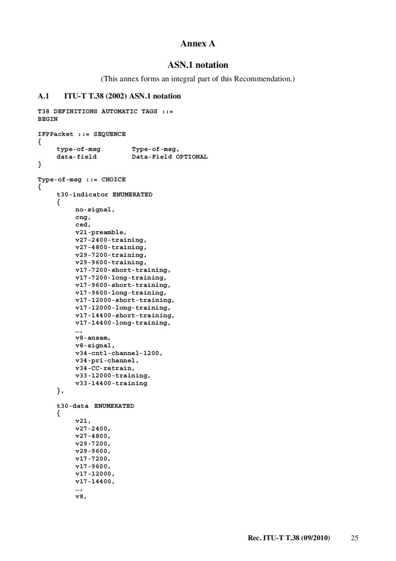
Annex A ASN.1 notation (This annex forms an integral part of this Recommendation.) A.1 ITU-T T.38 (2002) ASN.1 notation
T38 DEFINITIONS AUTOMATIC TAGS ::=
BEGIN
IFPPacket ::= SEQUENCE { type-of-msg Type-of-msg, data-field Data-Field OPTIONAL } Type-of-msg ::= CHOICE { t30-indicator ENUMERATED { no-signal, cng, ced, v21-preamble, v27-2400-training, v27-4800-training, v29-7200-training, v29-9600-training, v17-7200-short-training, v17-7200-long-training, v17-9600-short-training, v17-9600-long-training, v17-12000-short-training, v17-12000-long-training, v17-14400-short-training, v17-14400-long-training, …, v8-ansam, v8-signal, v34-cntl-channel-1200, v34-pri-channel, v34-CC-retrain, v33-12000-training, v33-14400-training }, t30-data ENUMERATED { v21, v27-2400, v27-4800, v29-7200, v29-9600, v17-7200, v17-9600, v17-12000, v17-14400, …, v8, Rec. ITU-T T.38 (09/2010) 25
Página 32 — T-REC-T.38-201009-IPDF-E-1
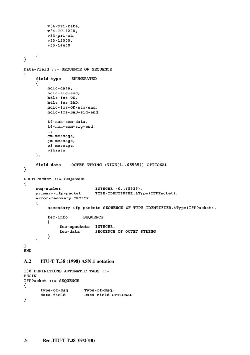
v34-pri-rate, v34-CC-1200, v34-pri-ch, v33-12000, v33-14400 } } Data-Field ::= SEQUENCE OF SEQUENCE { field-type
ENUMERATED
{ hdlc-data, hdlc-sig-end, hdlc-fcs-OK, hdlc-fcs-BAD, hdlc-fcs-OK-sig-end, hdlc-fcs-BAD-sig-end, t4-non-ecm-data, t4-non-ecm-sig-end, …, cm-message, jm-message, ci-message, v34rate }, field-data
OCTET STRING (SIZE(1..65535)) OPTIONAL
} UDPTLPacket ::= SEQUENCE { seq-number
INTEGER (0..65535),
primary-ifp-packet TYPE-IDENTIFIER.&Type(IFPPacket), error-recovery CHOICE { secondary-ifp-packets SEQUENCE OF TYPE-IDENTIFIER.&Type(IFPPacket), fec-info
SEQUENCE
{ fec-npackets INTEGER, fec-data
SEQUENCE OF OCTET STRING
} } } END A.2 ITU-T T.38 (1998) ASN.1 notation
T38 DEFINITIONS AUTOMATIC TAGS ::=
BEGIN
IFPPacket ::= SEQUENCE { type-of-msg Type-of-msg, data-field Data-Field OPTIONAL } 26 Rec. ITU-T T.38 (09/2010)
Página 33 — T-REC-T.38-201009-IPDF-E-1
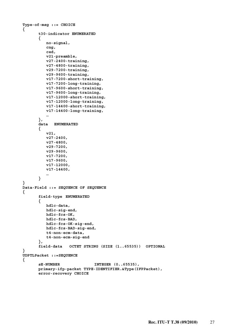
Type-of-msg ::= CHOICE { t30-indicator ENUMERATED { no-signal, cng, ced, v21-preamble, v27-2400-training, v27-4800-training, v29-7200-training, v29-9600-training, v17-7200-short-training, v17-7200-long-training, v17-9600-short-training, v17-9600-long-training, v17-12000-short-training, v17-12000-long-training, v17-14400-short-training, v17-14400-long-training, … }, data
ENUMERATED
{ v21, v27-2400, v27-4800, v29-7200, v29-9600, v17-7200, v17-9600, v17-12000, v17-14400, … } } Data-Field ::= SEQUENCE OF SEQUENCE { field-type ENUMERATED { hdlc-data, hdlc-sig-end, hdlc-fcs-OK, hdlc-fcs-BAD, hdlc-fcs-OK-sig-end, hdlc-fcs-BAD-sig-end, t4-non-ecm-data, t4-non-ecm-sig-end }, field-data
OCTET STRING (SIZE (1..65535)) OPTIONAL
} UDPTLPacket ::=SEQUENCE { sE-NUMBER
INTEGER (0..65535),
primary-ifp-packet TYPE-IDENTIFIER.&Type(IFPPacket), error-recovery CHOICE Rec. ITU-T T.38 (09/2010) 27
Página 34 — T-REC-T.38-201009-IPDF-E-1
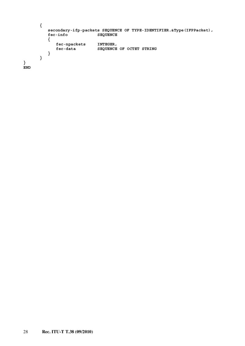
{ secondary-ifp-packets SEQUENCE OF TYPE-IDENTIFIER.&Type(IFPPacket), fec-info
SEQUENCE
{ fec-npackets
INTEGER,
fec-data
SEQUENCE OF OCTET STRING
} } } END 28 Rec. ITU-T T.38 (09/2010)
Página 35 — T-REC-T.38-201009-IPDF-E-1
Annex B ITU-T H.323 call establishment procedures (This annex forms an integral part of this Recommendation.) B.1 Introduction This annex describes system level requirements and procedures for Internet-aware facsimile implementations and Internet-aware facsimile gateways conforming to this Recommendation to establish calls with other ITU-T T.38 implementations including those using the procedures defined in this annex as well as Annex D of [ITU-T H.323].
B.2 Communication between facsimile terminal and gateway Communication between a sending Group 3 facsimile terminal and the incoming gateway is generally effected using dial-up procedures over the PSTN. Basic and optional ITU-T T.30 procedures are supported.
The gateway may receive the facsimile transmission from the calling terminal as a modem signal on the PSTN if the gateway supports a direct dial-in procedure. Where the gateway is located within the network, it may receive the transmission in the form of a PCM-encoded digital channel.
Internet-aware facsimile (IAF) implementations are connected directly to the IP network and act as a gateway for call establishment.
B.2.1
Transfer of addressing information The conveyance of the ITU-T E.164 address of the called terminal from the calling terminal to the emitting gateway may be by manual procedures using prompts, by means of double dialling, or by any other suitable means. In addition, there are some applications which may benefit from placing the destination ITU-T E.164 address in the IRA (Internet routing address)/ISP (Internet selective polling) signals, as described in [ITU-T T.30].
B.3 Communication between gateways
B.3.1
Overview
B.3.1.1
Call setup Call setup for ITU-T T.38 Annex B compliant implementations is based on the fast connect procedure defined in [ITU-T H.323]. ITU-T T.38 implementations may operate in two distinct ITU-T H.323 compatible environments.
1) A facsimile-only over IP environment. In this environment, no voice support is provided.
The procedures and requirements of this annex shall apply to implementations operating in this environment unless they are superseded by implementation of ITU-T H.323 Annex D.
2) A facsimile and voice over IP environment. Implementations in this environment shall use the methods described in Annex D of [ITU-T H.323].
ITU-T T.38 Annex B implementations shall use the fast connect procedure for call setup and shall not initiate ITU-T H.245 negotiation. However, ITU-T T.38 Annex B devices shall support ITU-T H.245 when the remote device is not an ITU-T T.38 Annex B device or otherwise needs to start ITU-T H.245.
Rec. ITU-T T.38 (09/2010) 29
Página 36 — T-REC-T.38-201009-IPDF-E-1
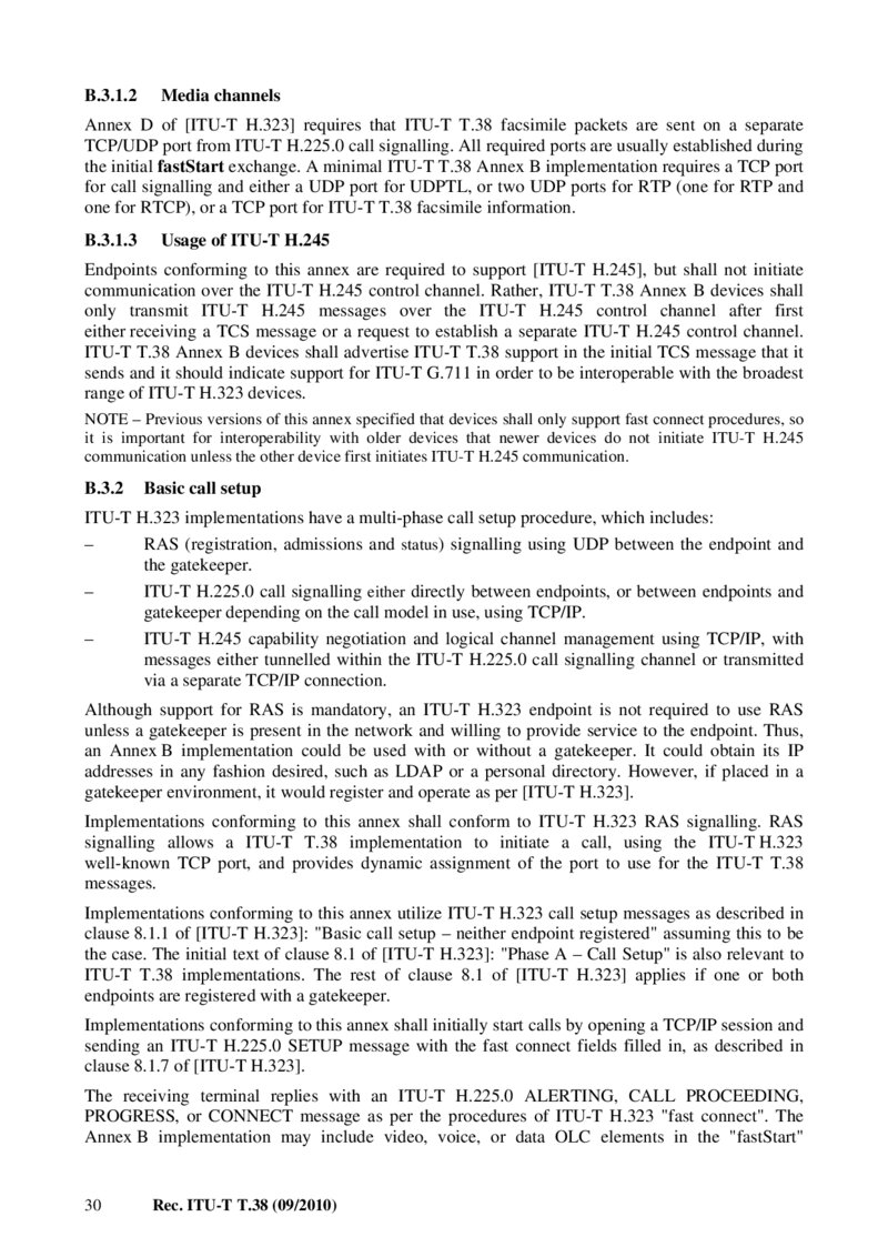
B.3.1.2
Media channels Annex D of [ITU-T H.323] requires that ITU-T T.38 facsimile packets are sent on a separate TCP/UDP port from ITU-T H.225.0 call signalling. All required ports are usually established during the initial fastStart exchange. A minimal ITU-T T.38 Annex B implementation requires a TCP port for call signalling and either a UDP port for UDPTL, or two UDP ports for RTP (one for RTP and one for RTCP), or a TCP port for ITU-T T.38 facsimile information.
B.3.1.3
Usage of ITU-T H.245 Endpoints conforming to this annex are required to support [ITU-T H.245], but shall not initiate communication over the ITU-T H.245 control channel. Rather, ITU-T T.38 Annex B devices shall only transmit ITU-T H.245 messages over the ITU-T H.245 control channel after first either receiving a TCS message or a request to establish a separate ITU-T H.245 control channel.
ITU-T T.38 Annex B devices shall advertise ITU-T T.38 support in the initial TCS message that it sends and it should indicate support for ITU-T G.711 in order to be interoperable with the broadest range of ITU-T H.323 devices.
NOTE – Previous versions of this annex specified that devices shall only support fast connect procedures, so it is important for interoperability with older devices that newer devices do not initiate ITU-T H.245 communication unless the other device first initiates ITU-T H.245 communication.
B.3.2
Basic call setup ITU-T H.323 implementations have a multi-phase call setup procedure, which includes:
– RAS (registration, admissions and status) signalling using UDP between the endpoint and the gatekeeper.
– ITU-T H.225.0 call signalling either directly between endpoints, or between endpoints and gatekeeper depending on the call model in use, using TCP/IP.
– ITU-T H.245 capability negotiation and logical channel management using TCP/IP, with messages either tunnelled within the ITU-T H.225.0 call signalling channel or transmitted via a separate TCP/IP connection.
Although support for RAS is mandatory, an ITU-T H.323 endpoint is not required to use RAS unless a gatekeeper is present in the network and willing to provide service to the endpoint. Thus, an Annex B implementation could be used with or without a gatekeeper. It could obtain its IP addresses in any fashion desired, such as LDAP or a personal directory. However, if placed in a gatekeeper environment, it would register and operate as per [ITU-T H.323].
Implementations conforming to this annex shall conform to ITU-T H.323 RAS signalling. RAS signalling allows a ITU-T T.38 implementation to initiate a call, using the ITU-T H.323 well-known TCP port, and provides dynamic assignment of the port to use for the ITU-T T.38 messages.
Implementations conforming to this annex utilize ITU-T H.323 call setup messages as described in clause 8.1.1 of [ITU-T H.323]: "Basic call setup – neither endpoint registered" assuming this to be the case. The initial text of clause 8.1 of [ITU-T H.323]: "Phase A – Call Setup" is also relevant to ITU-T T.38 implementations. The rest of clause 8.1 of [ITU-T H.323] applies if one or both endpoints are registered with a gatekeeper.
Implementations conforming to this annex shall initially start calls by opening a TCP/IP session and sending an ITU-T H.225.0 SETUP message with the fast connect fields filled in, as described in clause 8.1.7 of [ITU-T H.323].
The receiving terminal replies with an ITU-T H.225.0 ALERTING, CALL PROCEEDING, PROGRESS, or CONNECT message as per the procedures of ITU-T H.323 "fast connect". The Annex B implementation may include video, voice, or data OLC elements in the "fastStart" 30 Rec. ITU-T T.38 (09/2010)
Página 37 — T-REC-T.38-201009-IPDF-E-1
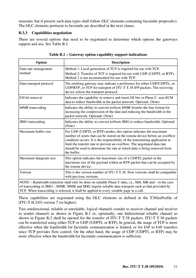
structure, but if present such data types shall follow OLC elements containing facsimile proposal(s).
The OLC elements pertinent to facsimile are described in the next clause.
B.3.3
Capabilities negotiation There are several options that need to be negotiated to determine which options the gateways support and use. See Table B.1.
Table B.1 – Gateway option capability support indications Option Description Data rate management method Method 1: Local generation of TCF is required for use with TCP.
Method 2: Transfer of TCF is required for use with UDP (UDPTL or RTP).
Method 2 is not recommended for use with TCP.
Data transport protocol The emitting gateway may indicate a preference for either UDP/UDPTL, or UDP/RTP, or TCP for transport of ITU-T T.38 IFP packets. The receiving device selects the transport protocol.
Fill bit removal Indicates the capability to remove and insert fill bits in Phase C, non-ECM data to reduce bandwidth in the packet network. Optional. (Note) MMR transcoding Indicates the ability to convert to/from MMR from/to the line format for increasing the compression of the data and reducing the bandwidth in the packet network. Optional. (Note) JBIG transcoding Indicates the ability to convert to/from JBIG to reduce bandwidth. Optional.
(Note) Maximum buffer size For UDP (UDPTL or RTP) modes, this option indicates the maximum number of octets that can be stored on the remote device before an overflow condition occurs. It is the responsibility of the transmitting application to limit the transfer rate to prevent an overflow. The negotiated data rate should be used to determine the rate at which data is being removed from the buffer.
Maximum datagram size This option indicates the maximum size of a UDPTL packet or the maximum size of the payload within an RTP packet that can be accepted by the remote device.
Version This is the version number of ITU-T T.38. New versions shall be compatible with previous versions.
NOTE – Bandwidth reduction shall only be done on suitable Phase C data, i.e., MH, MR and – in the case of transcoding to JBIG – MMR. MMR and JBIG require reliable data transport such as that provided by TCP. When transcoding is selected, it shall be applied to every suitable page in a call.
These capabilities are negotiated using the OLC elements as defined in the T38faxProfile of [ITU-T H.245] version 7 (or higher).
Two unidirectional, reliable or unreliable, logical channels (sender to receiver channel and receiver to sender channel) as shown in Figure B.1 or, optionally, one bidirectional reliable channel as shown in Figure B.2 shall be opened for the transfer of ITU-T T.38 packets. ITU-T T.38 packets can be transferred using either TCP or UDP (UDPTL or RTP). In general, the usage of TCP is more effective when the bandwidth for facsimile communication is limited, or for IAF to IAF transfers since TCP provides flow control. On the other hand, the usage of UDP (UDPTL or RTP) may be more effective when the bandwidth for facsimile communication is sufficient.
Rec. ITU-T T.38 (09/2010) 31
Página 38 — T-REC-T.38-201009-IPDF-E-1
T.38_FB.1
Figure B.1 – A pair of unidirectional channels
T.38_FB.2
Figure B.2 – A single bidirectional channel The sender terminal specifies a TCP/UDP port in the OpenLogicalChannel in the fastStart element of Setup when transmitting T.38 via TCP or UDPTL. The receiver terminal shall provide its TCP (or UDP) port in the OpenLogicalChannel of the fastStart element as specified by the procedures in clause 8.1.7 of [ITU-T H.323]: "Fast connect".
The receiver should open the TCP/UDP port based on the preference of the sender. If the sender terminal has a preference for UDP (UDPTL or RTP) or TCP, then it shall provide its preference in the OpenLogicalChannel with the appropriate port in the fastStart sequence. The receiving terminal can select the transport, TCP or UDP (UDPTL or RTP), by specifying one of the two in OpenLogicalChannel structures in the fastStart element of Connect.
When transmitting ITU-T T.38 over RTP, the OpenLogicalChannel contains the generic audio capability defined in Annex G and shall be included in the fastStart element in the Setup message as specified in clause 8.1.7 of [ITU-T H.323]: "Fast Connect". The parameter names in the generic audio capability are named the same as those used in the ITU-T H.245 ASN.1.
All ITU-T T.38 Annex B implementations shall include a T38fax OLC with t38FaxUdpOptions and transferredTCF set in the fastStart structure. Note that all ITU-T H.323 Annex D devices supporting ITU-T T.38 also are required to include these structures. In addition, ITU-T T.38 Annex B devices should include an OLC with t38FaxTcpOptions and localTCF set and with tcp selected as the t38FaxProtocol choice. Optionally, ITU-T T.38 Annex B devices may include an OLC with the T38RTP generic audio capability specified with the transferredTCF included in the fastStart structure. As described in clause 8.1.7 of [ITU-T H.323], the order in which OLCs are included in the fastStart element indicates preference on the part of the sender. The receiver only includes the OLCs that it wishes to use in the fastStart element of the CONNECT message or other message containing the fastStart element.
NOTE – In the first version of this annex, it was not possible to use a single bidirectional reliable channel. In order to retain backward compatibility, the endpoint may specify support for bidirectional reliable channels by including the t38FaxTcpOptions SEQUENCE and setting the t38TCPBidirectionalMode field to TRUE.
If the other endpoint does not include the t38FaxTcpOptions SEQUENCE, the endpoint shall assume that a single bidirectional reliable channel for ITU-T T.38 is not supported and shall use either two unidirectional reliable or unreliable channels.
32 Rec. ITU-T T.38 (09/2010)
Página 39 — T-REC-T.38-201009-IPDF-E-1
B.3.4
Examples of call setup OLCs The examples in this clause illustrate the OLC elements that are sent in various cases. The rules of clause 8.1.7 of [ITU-T H.323] are followed using OLC definitions in [ITU-T H.245]. Refer to [ITU-T H.245] for the relevant ASN.1.
B.3.4.1
TCP, UDP (UDPTL), or RTP support The default case requires support for both TCP and UDP (UDPTL). In this case, the sender shall send OLCs for T38/TCP&localTCF and T38/UDPTL&transferredTCF. Optionally, the sender may send OLCs for T38RTP&transferredTCF. If the receiver wishes to use UDP, an OLC for T38/UDPTL&transferredTCF is returned. If the receiver wishes to use RTP, an OLC for T38RTP&transferredTCF is returned. Otherwise, the OLC for T38/TCP&localTCF is returned.
B.3.4.2
UDP (UDPTL) with data rate management method 1 support For the case where the sender wishes to use data rate management method 1 and UDP (UDPTL) for data transport, it shall send OLCs for T38/UDPTL&transferredTCF, T38/UDPTL&localTCF, T38/TCP&localTCF. If the receiver agrees to use UDPTL&localTCF, an OLC for T38/UDPTL&localTCF is returned.
B.3.4.3
RTP with data rate management method 1 support For the case where the sender wishes to use data rate management method 1 and RTP for data transport, it shall send OLCs for T38RTP&transferredTCF and T38RTP&localTCF. If the receiver agrees to use RTP&localTCF, an OLC for T38RTP&localTCF is returned.
B.3.5
Mandatory call setup messages The Annex B implementation shall support the following clauses of [ITU-T H.225.0] for call setup:
– Mandatory elements in Table 4 of [ITU-T H.225.0], i.e., ALERTING, CONNECT, CALL PROCEEDING, SETUP, RELEASE COMPLETE, etc., shall be supported by ITU-T T.38 endpoints conforming to Annex B. Note that there is no requirement to send ALERTING if CONNECT, CALL PROCEEDING, or RELEASE COMPLETE is sent within 4 seconds of the receipt of SETUP, as described in [ITU-T H.323]. Note also that gateways shall send
CALL PROCEEDING.
– The Information elements of FACILITY, as described in clause 7.4.1 of [ITU-T H.225.0].
– The Information elements of ALERTING, as described in clause 7.3.1 of [ITU-T H.225.0].
– The Information elements of CALL PROCEEDING, as described in clause 7.3.2 of
[ITU-T H.225.0].
– The Information elements of CONNECT, as described in clause 7.3.3 of [ITU-T H.225.0].
– The information elements of PROGRESS, as described in clause 7.3.7 of [ITU-T H.225.0].
– The Information elements of RELEASE COMPLETE, as described in clause 7.3.9 of
[ITU-T H.225.0].
– The Information elements of SETUP, as described in clause 7.3.10 of [ITU-T H.225.0].
– The ASN.1 of [ITU-T H.225.0], as described in [ITU-T H.225.0].
NOTE – ITU-T H.225.0 ASN.1 supports a large number of optional features. ITU-T T.38 Annex B implementations may implement the full range of optional ITU-T H.225.0 features, including authentication features that are potentially available. They may also implement ITU-T H.450.x supplementary services.
ITU-T H.225.0 options are outside (i.e., prior) to the OLC negotiations. If a real time fax endpoint ([ITU-T H.323] Annex D or [ITU-T T.38] Annex B) makes use of ITU-T H.450.x supplementary services, it must take into account that the remote endpoint may or may not support them. In the worst case, the supplementary service is ignored by the receiver. Thus the requesting endpoint must handle this condition, with, for example, a timeout mechanism.
Rec. ITU-T T.38 (09/2010) 33
Página 40 — T-REC-T.38-201009-IPDF-E-1
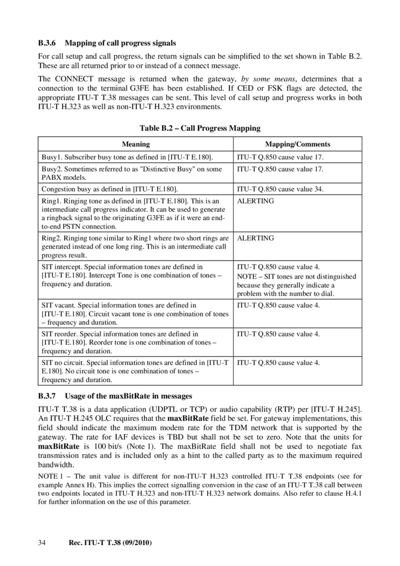
B.3.6
Mapping of call progress signals For call setup and call progress, the return signals can be simplified to the set shown in Table B.2.
These are all returned prior to or instead of a connect message.
The CONNECT message is returned when the gateway, by some means, determines that a connection to the terminal G3FE has been established. If CED or FSK flags are detected, the appropriate ITU-T T.38 messages can be sent. This level of call setup and progress works in both ITU-T H.323 as well as non-ITU-T H.323 environments.
Table B.2 – Call Progress Mapping Meaning Mapping/Comments Busy1. Subscriber busy tone as defined in [ITU-T E.180].
ITU-T Q.850 cause value 17. Busy2. Sometimes referred to as "Distinctive Busy" on some PABX models.
ITU-T Q.850 cause value 17. Congestion busy as defined in [ITU-T E.180].
ITU-T Q.850 cause value 34. Ring1. Ringing tone as defined in [ITU-T E.180]. This is an intermediate call progress indicator. It can be used to generate a ringback signal to the originating G3FE as if it were an endto-end PSTN connection.
ALERTING
Ring2. Ringing tone similar to Ring1 where two short rings are generated instead of one long ring. This is an intermediate call progress result.
ALERTING
SIT intercept. Special information tones are defined in [ITU-T E.180]. Intercept Tone is one combination of tones – frequency and duration.
ITU-T Q.850 cause value 4. NOTE – SIT tones are not distinguished because they generally indicate a problem with the number to dial.
SIT vacant. Special information tones are defined in [ITU-T E.180]. Circuit vacant tone is one combination of tones – frequency and duration.
ITU-T Q.850 cause value 4. SIT reorder. Special information tones are defined in [ITU-T E.180]. Reorder tone is one combination of tones – frequency and duration.
ITU-T Q.850 cause value 4. SIT no circuit. Special information tones are defined in [ITU-T E.180]. No circuit tone is one combination of tones – frequency and duration.
ITU-T Q.850 cause value 4.
B.3.7
Usage of the maxBitRate in messages ITU-T T.38 is a data application (UDPTL or TCP) or audio capability (RTP) per [ITU-T H.245].
An ITU-T H.245 OLC requires that the maxBitRate field be set. For gateway implementations, this field should indicate the maximum modem rate for the TDM network that is supported by the gateway. The rate for IAF devices is TBD but shall not be set to zero. Note that the units for maxBitRate is 100 bit/s (Note 1). The maxBitRate field shall not be used to negotiate fax transmission rates and is included only as a hint to the called party as to the maximum required bandwidth.
NOTE 1 – The unit value is different for non-ITU-T H.323 controlled ITU-T T.38 endpoints (see for example Annex H). This implies the correct signalling conversion in the case of an ITU-T T.38 call between two endpoints located in ITU-T H.323 and non-ITU-T H.323 network domains. Also refer to clause H.4.1 for further information on the use of this parameter.
34 Rec. ITU-T T.38 (09/2010)
Página 41 — T-REC-T.38-201009-IPDF-E-1
B.3.8
DTMF transmission UserInputIndication as described in Annex D of [ITU-T H.323] is an ITU-T H.245 signal and may be used if the ITU-T H.245 control channel is utilized. Other mechanisms as described in [ITU-T H.323] or [ITU-T H.225.0] may also be employed.
B.3.9
Interoperability Both ITU-T H.323 direct call model and ITU-T T.38 Annex B require a well-known port to initiate call signalling. As described in Appendix IV of [ITU-T H.225.0], the ITU-T H.323 well-known port for call signalling via TCP is 1720. ITU-T T.38 Annex B endpoints should use the ITU-T H.323 well-known port. In order for a single implementation (such as a gateway) to support multiple endpoints, dynamic ports must be used. A facsimile gateway conforming to this annex shall support
ITU-T H.323 RAS.
ITU-T T.38 Annex B implementations shall set h245Tunnelling to TRUE in all ITU-T H.225.0 messages.
Rec. ITU-T T.38 (09/2010) 35
Página 42 — T-REC-T.38-201009-IPDF-E-1
Annex C The optional forward error correction scheme for UDPTL (This annex forms an integral part of this Recommendation.) C.1 Overview of the optional forward error correction mechanism The parity FEC scheme is symmetrical in that it is identical in both encode and decode modes, and may be computed for an arbitrary number of arbitrarily sized IFP messages. A transmitting gateway generates FEC messages by passing in a number of primary IFP packets; these FEC messages may then be assembled into a packet in accordance with Figure 5.
Receiving gateways which detect the loss of a primary IFP packet that is covered by an FEC message may be able to reconstruct it by passing in the remaining (received) primary IFP packets and the FEC message itself to the parity encode/decode algorithm. Certain conditions apply in order for a lost primary IFP packet to be recovered using the parity encoder/decoder; these shall be discussed in the following clauses.
C.2 Parity encode/decode scheme operation and characteristics The parity scheme accepts a number of arbitrarily sized IFP messages. It aligns them vertically and zero pads the shorter length messages to produce a 2D matrix as shown in Figure C.1 a). A one-bit piece-wise sum is then performed on a column by column basis (equivalent to exclusive OR logic function) across the width of the matrix, each summation resulting in a binary digit. This process is illustrated in Figure C.1 b). The output from the parity scheme is the row of resulting binary data.
The basic error recovery scheme works by assuming that 1 loss in n packets may occur. If the (n + 1)th packet contains an FEC message generated from the primary IFP packets of the n preceding packets, then provided no more than one of the first n packets is lost, any missing IFP message can be reconstructed. The generation and reconstruction of primary IFP packets using the parity scheme outlined above is described in the following subclauses.
36 Rec. ITU-T T.38 (09/2010)
Página 43 — T-REC-T.38-201009-IPDF-E-1
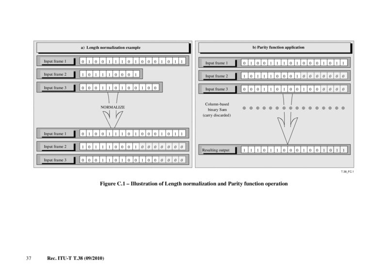
b) Parity function application a) Length normalization example Input frame 1 0 1 0 0 1 1 1 0 1 Input frame 2 1 0 1 1 1 0 0 0 1 Input frame 3 0 0 0 1 1 0 1 0 0 0 1 0 0 0 1 0 1 1 0
NORMALIZE
Input frame 1 0 1 0 0 1 1 1 0 1 0 0 0 1 0 1 1 Input frame 2 1 0 1 1 1 0 0 0 1 0 0 0 0 0 0 0 0 0 0 1 1 0 1 0 0 1 0 0 0 0 0 0 Input frame 3 Input frame 1 0 1 0 0 1 1 1 0 1 0 0 0 1 0 1 1 Input frame 2 1 0 1 1 1 0 0 0 1 0 0 0 0 0 0 0 Input frame 3 0 0 0 1 1 0 1 0 0 1 0 0 0 0 0 0 Column-based binary Sum (carry discarded) ⊕ ⊕ ⊕ ⊕ ⊕ ⊕ ⊕ ⊕ ⊕ ⊕ ⊕ ⊕ ⊕ ⊕ ⊕ ⊕ Resulting output 1 1 1 0 1 1 0 0 0 1 0 0 1 0 1 1
T.38_FC.1
Figure C.1 – Illustration of Length normalization and Parity function operation 37 Rec. ITU-T T.38 (09/2010)
Página 44 — T-REC-T.38-201009-IPDF-E-1
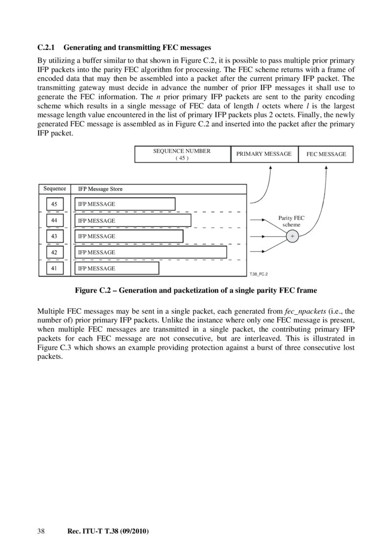
C.2.1
Generating and transmitting FEC messages By utilizing a buffer similar to that shown in Figure C.2, it is possible to pass multiple prior primary IFP packets into the parity FEC algorithm for processing. The FEC scheme returns with a frame of encoded data that may then be assembled into a packet after the current primary IFP packet. The transmitting gateway must decide in advance the number of prior IFP messages it shall use to generate the FEC information. The n prior primary IFP packets are sent to the parity encoding scheme which results in a single message of FEC data of length l octets where l is the largest message length value encountered in the list of primary IFP packets plus 2 octets. Finally, the newly generated FEC message is assembled as in Figure C.2 and inserted into the packet after the primary IFP packet.
SEQUENCE NUMBER
( 45 )
PRIMARY MESSAGE
FEC MESSAGE
IFP MESSAGE
Parity FEC scheme
IFP MESSAGE
IFP MESSAGE
IFP MESSAGE
IFP MESSAGE
T.38_FC.2
Figure C.2 – Generation and packetization of a single parity FEC frame Multiple FEC messages may be sent in a single packet, each generated from fec_npackets (i.e., the number of) prior primary IFP packets. Unlike the instance where only one FEC message is present, when multiple FEC messages are transmitted in a single packet, the contributing primary IFP packets for each FEC message are not consecutive, but are interleaved. This is illustrated in Figure C.3 which shows an example providing protection against a burst of three consecutive lost packets.
38 Rec. ITU-T T.38 (09/2010)
Página 45 — T-REC-T.38-201009-IPDF-E-1
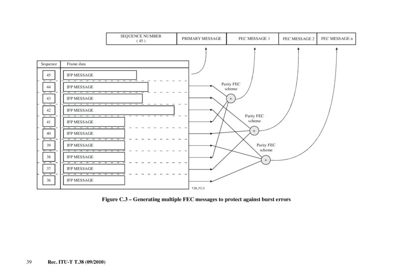
SEQUENCE NUMBER
( 45 ) Sequence
PRIMARY MESSAGE
FEC MESSAGE 1
FEC MESSAGE 2
Frame data 45
IFP MESSAGE
44
IFP MESSAGE
Parity FEC scheme 43
IFP MESSAGE
42
IFP MESSAGE
41
IFP MESSAGE
40
IFP MESSAGE
39
IFP MESSAGE
38
IFP MESSAGE
37
IFP MESSAGE
36
IFP MESSAGE
Parity FEC scheme Parity FEC scheme
T.38_FC.3
Figure C.3 – Generating multiple FEC messages to protect against burst errors 39 Rec. ITU-T T.38 (09/2010) FEC MESSAGE n
Página 46 — T-REC-T.38-201009-IPDF-E-1
C.2.2
Receiving FEC messages and primary IFP packet reconstruction A gateway in receipt of FEC messages in a packet must determine from the UDPTL packet:
the number of FEC messages present in the packet; the sequence numbers of the primary IFP packets contained in each FEC message; the sequence numbers of any packets which have been "lost" over the network.
In order to determine the sequence numbers of the primary IFP packets encoded in a given FEC message, the receiving gateway must extract the number of primary IFP packets covered by that frame. For a packet containing a single FEC message, the sequence numbers covered by that message are simply those from [Seq – 1] to [Seq – (n + 1)] where n is the value in the fec_npackets element and Seq is the value in the seq-number element. For a UDPTL packet containing m FEC messages with sequence number Seq and a message control field setting of n, the sequence number ranges for FEC message I (for 1 ≤ I ≤ m) are trivially extracted from the following equations:
StartSeq = Seq – I EndSeq = Seq – I – (n – 1)m Intermediate sequence numbers between these ranges are linearly spaced with gap m. Once the sequence numbers of the primary IFP packets encoded in an FEC message have been determined, the receiving gateway may check to determine whether any of the primary IFP packets listed has failed to arrive. If one, and only one, of these primary IFP packets has failed to arrive, then the FEC message and the remaining (delivered) primary IFP packets may be sent to the parity algorithm to recover the missing sequence.
The number of FEC messages, m, is the number of octet strings contained in the fec-data element (as encoded in the SEQUENCE OF construct).
40 Rec. ITU-T T.38 (09/2010)
Página 47 — T-REC-T.38-201009-IPDF-E-1
Annex D SIP/SDP call establishment procedures (This annex forms an integral part of this Recommendation.) D.1 Introduction This annex describes system level requirements and procedures for Internet-aware facsimile implementations and Internet-aware facsimile gateways conforming to ITU-T T.38 to establish calls with other ITU-T T.38 implementations using the procedures defined in [IETF RFC 3261] (SIP) and [IETF RFC 2327] (SDP). SIP [IETF RFC 3261] uses the embedded SDP Offer/Answer protocol (see clause D.2.3.0) for indication and negotiation of media configurations (for example, a specific ITU-T T.38 configuration).
D.2 Communication between gateways
D.2.1
Overview
D.2.1.1
Call setup Call setup for Annex D of ITU-T T.38 compliant implementation is based on SIP (session initiation protocol) defined in [IETF RFC 3261]. As in Annex B, implementations may operate in two distinct compatible environments:
1) A facsimile-only over IP environment − In this environment, no voice support is provided.
The procedures and requirements of D.2.2.3 shall apply to implementations operating in this environment.
2) A facsimile and voice over IP environment − The procedures and requirements of this annex shall apply to implementations operating in this environment.
D.2.1.2
Media and signalling channels NOTE – The term "channel" is reused from ITU-T H.323 terminology (see Annex B), and is synonymous with "IP transport connection" in this annex.
ITU-T T.38 facsimile packets are sent on a separate TCP/UDP port from SIP call signalling. A minimal Annex D of ITU-T T.38 implementation requires:
– for the IP transport connection for SIP: a TCP/UDP port (default is 5060) for call signalling; and – for the IP transport connection for media (depending on the ITU-T T.38 transport mode):
• a UDP port for "UDPTL/UDP"; • one or two UDP ports for "RTP/UDP" (depending on RTCP usage); or • a TCP port for "TPKT/TCP" for ITU-T T.38 facsimile information
D.2.1.3
Usage of SDP Endpoints conforming to this annex are required to support SDP, including the extensions described below.
D.2.1.3.1 SDP parameter definitions The SDP parameters shown in Table D.1 are defined by this Recommendation.
Rec. ITU-T T.38 (09/2010) 41
Página 48 — T-REC-T.38-201009-IPDF-E-1
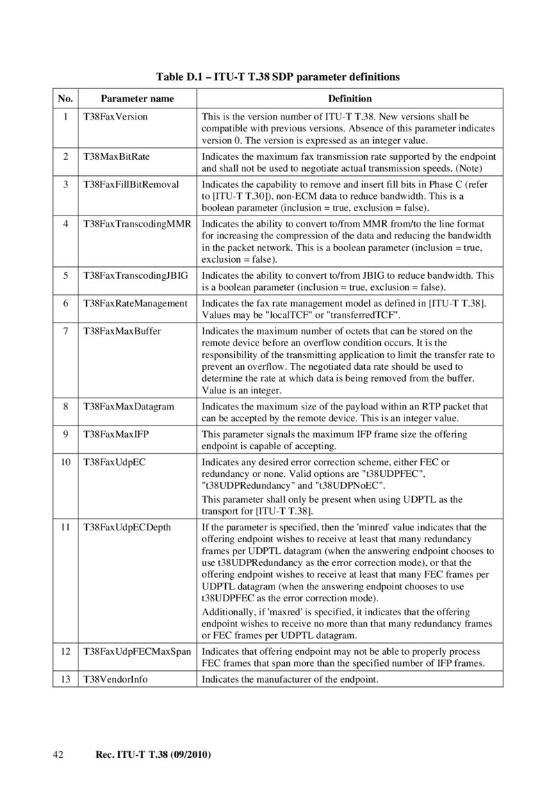
Table D.1 – ITU-T T.38 SDP parameter definitions No.
Parameter name Definition 1 T38FaxVersion This is the version number of ITU-T T.38. New versions shall be compatible with previous versions. Absence of this parameter indicates version 0. The version is expressed as an integer value.
2 T38MaxBitRate Indicates the maximum fax transmission rate supported by the endpoint and shall not be used to negotiate actual transmission speeds. (Note) 3 T38FaxFillBitRemoval Indicates the capability to remove and insert fill bits in Phase C (refer to [ITU-T T.30]), non-ECM data to reduce bandwidth. This is a boolean parameter (inclusion = true, exclusion = false).
4 T38FaxTranscodingMMR Indicates the ability to convert to/from MMR from/to the line format for increasing the compression of the data and reducing the bandwidth in the packet network. This is a boolean parameter (inclusion = true, exclusion = false).
5 T38FaxTranscodingJBIG Indicates the ability to convert to/from JBIG to reduce bandwidth. This is a boolean parameter (inclusion = true, exclusion = false).
6 T38FaxRateManagement Indicates the fax rate management model as defined in [ITU-T T.38].
Values may be "localTCF" or "transferredTCF".
7 T38FaxMaxBuffer Indicates the maximum number of octets that can be stored on the remote device before an overflow condition occurs. It is the responsibility of the transmitting application to limit the transfer rate to prevent an overflow. The negotiated data rate should be used to determine the rate at which data is being removed from the buffer.
Value is an integer. 8 T38FaxMaxDatagram Indicates the maximum size of the payload within an RTP packet that can be accepted by the remote device. This is an integer value.
9 T38FaxMaxIFP This parameter signals the maximum IFP frame size the offering endpoint is capable of accepting.
10 T38FaxUdpEC Indicates any desired error correction scheme, either FEC or redundancy or none. Valid options are "t38UDPFEC", "t38UDPRedundancy" and "t38UDPNoEC".
This parameter shall only be present when using UDPTL as the transport for [ITU-T T.38].
11 T38FaxUdpECDepth If the parameter is specified, then the 'minred' value indicates that the offering endpoint wishes to receive at least that many redundancy frames per UDPTL datagram (when the answering endpoint chooses to use t38UDPRedundancy as the error correction mode), or that the offering endpoint wishes to receive at least that many FEC frames per UDPTL datagram (when the answering endpoint chooses to use t38UDPFEC as the error correction mode).
Additionally, if 'maxred' is specified, it indicates that the offering endpoint wishes to receive no more than that many redundancy frames or FEC frames per UDPTL datagram.
12 T38FaxUdpFECMaxSpan Indicates that offering endpoint may not be able to properly process FEC frames that span more than the specified number of IFP frames.
13 T38VendorInfo Indicates the manufacturer of the endpoint.
42 Rec. ITU-T T.38 (09/2010)
Página 49 — T-REC-T.38-201009-IPDF-E-1
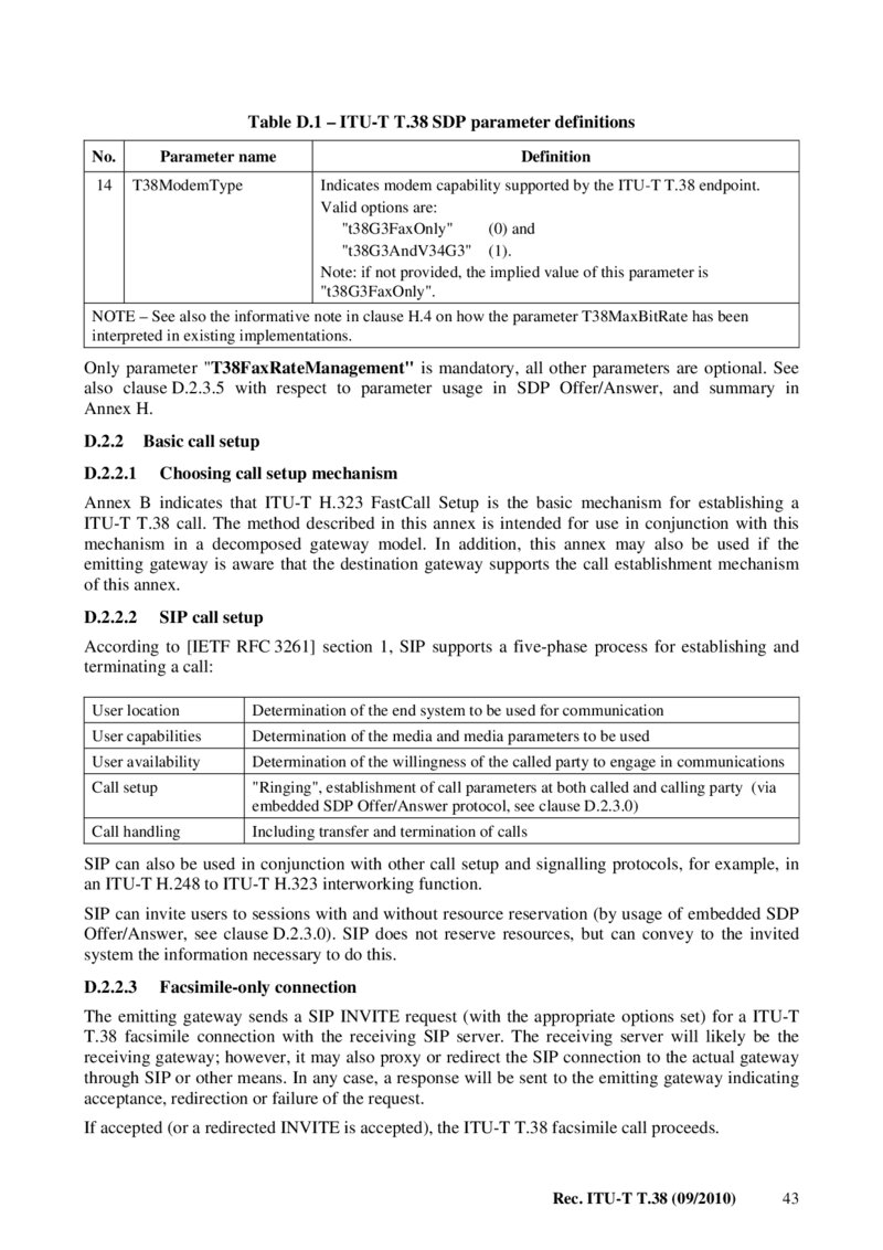
Table D.1 – ITU-T T.38 SDP parameter definitions No.
14 Parameter name T38ModemType Definition Indicates modem capability supported by the ITU-T T.38 endpoint.
Valid options are: "t38G3FaxOnly" (0) and "t38G3AndV34G3" (1).
Note: if not provided, the implied value of this parameter is "t38G3FaxOnly".
NOTE – See also the informative note in clause H.4 on how the parameter T38MaxBitRate has been interpreted in existing implementations.
Only parameter "T38FaxRateManagement" is mandatory, all other parameters are optional. See also clause D.2.3.5 with respect to parameter usage in SDP Offer/Answer, and summary in Annex H.
D.2.2
Basic call setup
D.2.2.1
Choosing call setup mechanism Annex B indicates that ITU-T H.323 FastCall Setup is the basic mechanism for establishing a ITU-T T.38 call. The method described in this annex is intended for use in conjunction with this mechanism in a decomposed gateway model. In addition, this annex may also be used if the emitting gateway is aware that the destination gateway supports the call establishment mechanism of this annex.
D.2.2.2
SIP call setup According to [IETF RFC 3261] section 1, SIP supports a five-phase process for establishing and terminating a call:
User location Determination of the end system to be used for communication User capabilities Determination of the media and media parameters to be used User availability Determination of the willingness of the called party to engage in communications Call setup "Ringing", establishment of call parameters at both called and calling party (via embedded SDP Offer/Answer protocol, see clause D.2.3.0) Call handling Including transfer and termination of calls SIP can also be used in conjunction with other call setup and signalling protocols, for example, in an ITU-T H.248 to ITU-T H.323 interworking function.
SIP can invite users to sessions with and without resource reservation (by usage of embedded SDP Offer/Answer, see clause D.2.3.0). SIP does not reserve resources, but can convey to the invited system the information necessary to do this.
D.2.2.3
Facsimile-only connection The emitting gateway sends a SIP INVITE request (with the appropriate options set) for a ITU-T T.38 facsimile connection with the receiving SIP server. The receiving server will likely be the receiving gateway; however, it may also proxy or redirect the SIP connection to the actual gateway through SIP or other means. In any case, a response will be sent to the emitting gateway indicating acceptance, redirection or failure of the request.
If accepted (or a redirected INVITE is accepted), the ITU-T T.38 facsimile call proceeds.
Rec. ITU-T T.38 (09/2010) 43
Página 50 — T-REC-T.38-201009-IPDF-E-1
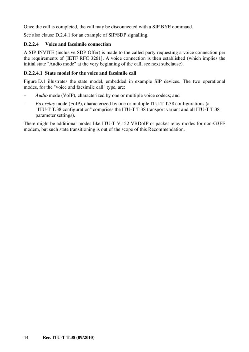
Once the call is completed, the call may be disconnected with a SIP BYE command.
See also clause D.2.4.1 for an example of SIP/SDP signalling.
D.2.2.4
Voice and facsimile connection A SIP INVITE (inclusive SDP Offer) is made to the called party requesting a voice connection per the requirements of [IETF RFC 3261]. A voice connection is then established (which implies the initial state "Audio mode" at the very beginning of the call, see next subclause).
D.2.2.4.1 State model for the voice and facsimile call Figure D.1 illustrates the state model, embedded in example SIP devices. The two operational modes, for the "voice and facsimile call" type, are:
– Audio mode (VoIP), characterized by one or multiple voice codecs; and – Fax relay mode (FoIP), characterized by one or multiple ITU-T T.38 configurations (a "ITU-T T.38 configuration" comprises the ITU-T T.38 transport variant and all ITU-T T.38 parameter settings).
There might be additional modes like ITU-T V.152 VBDoIP or packet relay modes for non-G3FE modem, but such state transitioning is out of the scope of this Recommendation.
44 Rec. ITU-T T.38 (09/2010)
Este PDF tiene 157 páginas. Se muestran las primeras 50.